2019 polaris rzr tail light power harness get this product. Pvt system transmission final drive steering suspension brake system body frame electrical wiring diagrams.
655b0 Brake Light Wiring Diagram Chevy Manual Wiring Library
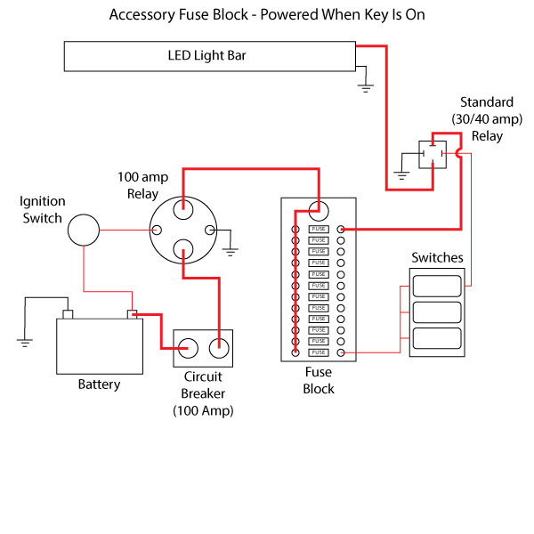
Rzr brake light wiring diagram. Our off road vehicles take you where others cant. Shop the variety of quality sxs electrical harnesses from the official polaris rzr store. You can read up on the brake light issue on several turn signal controller web site. It reveals the parts of the circuit as streamlined shapes and also the power and signal connections in between the tools. Collection of 2015 polaris rzr 900 wiring diagram. I believe when you have a turn signal on the controller then voids power to the brake light on the side with the turn signal flashing.
Variety of universal turn signal wiring diagram. Polaris rzr xp turbo dynamix edition 2018 models. It shows the parts of the circuit as simplified forms and also the power and also signal links in between the devices. Unlimited rider 3 wire rear tail light power harness connector plug and play light wiring for polaris 2015 2019 rzr 900 1000 xp turbo whip running lightbrake lightlicense plate light 40 out of 5 stars 6. A wiring diagram is a streamlined standard pictorial depiction of an electrical circuit. Service repair workshop manual.
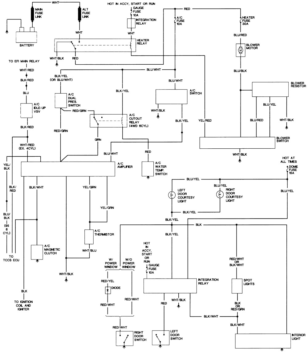
The turn signal controller for my rzr 800 didnt have the brake lite issue as i used a different bulb for the turn. P8 is wiring diagram of the tailbrake light harness. On my 2013 rzr xp900 the rdye wire is hot with ignition switch on. The or wire becomes the ground when the brake is applied. Your relay diagram unless the brown wire is a ground from the rzr you have no way to energise the relay so your 12 volt path is directly to the brake lights. Httpsamznto2jvyqvu 1 minute install can run 2 harnesses per vehicle fits 2015 2016 2017 and 2018 polaris rzr 9001000 xp 1000.
A wiring diagram is a streamlined standard pictorial depiction of an electric circuit. You need 12 and ground on pins 85 and 86 to turn on the relay so pin 30 can connect to 87 no when on and 87nc when off.
Gallery of Rzr Brake Light Wiring Diagram