In this document we will explain how to wire our gsm unit to an ids panel for alarm trigger and armdisarm triggering. Normally closed nc sensors and end of line resistors eolr wiring an alarm system how to connect the wires to sensors and the alarm panel.

Electrical Basics Of Fire Alarms And Sprinklers
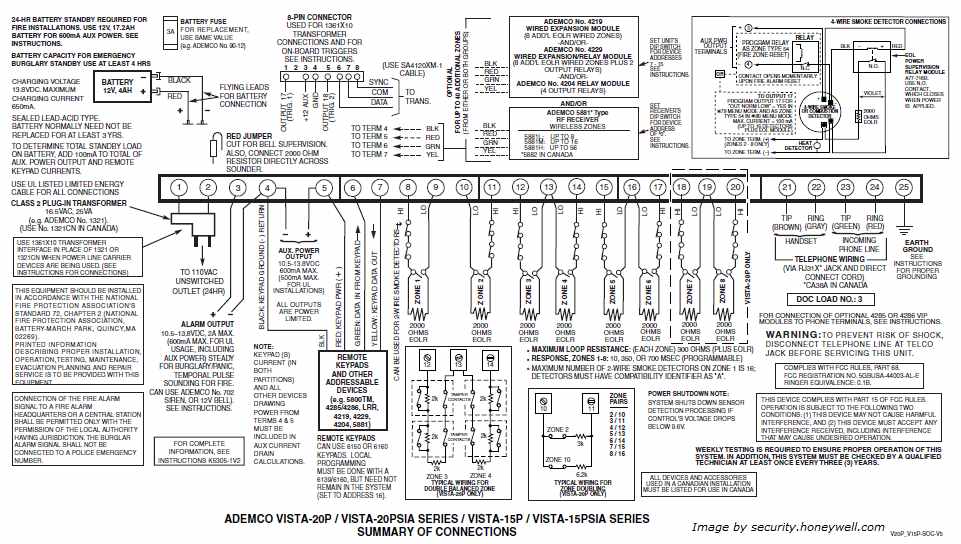
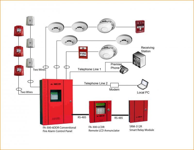
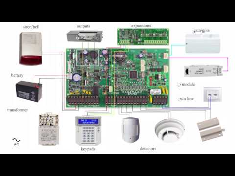
Alarm panel wiring diagram. Content with alarm video and other electronics is moved to a channel. It reveals the parts of the circuit as streamlined shapes as well as the power and signal connections in between the devices. This page focuses on the wiring needed for main panel functions. Connect these wires to the black and red wires of the alarm wire that runs back to the and bell terminals on the main panel. Indicating appliance circuits connect the fire alarm panel to the components which alert building occupants of the fire ie bells horns speakers strobe lights etc. For this example the siren also has an optional yellow wire that can be used instead of the red wire.
The types of wiring to use are listed at the bottom of the page. In our basic wiring diagram a single or multiple heat and smoke detectors are installed in the home by connecting the live line or hot neutral ground and an interconnected wire to the alarm. Wiring a home alarm system is easiest to do while the house is being built but it can also be done in an existing home. Home alarm wiring is needed to interconnect the parts of all hardwired home security systemsthe main alarm panel needs wiring to all home security components in the system as well as to power telephone and any other input or output devices you may want. A smoke or heat detector can be installed to the existing or new home wiring. For an overview of wires needed for the complete system see this page on home alarm wiring.
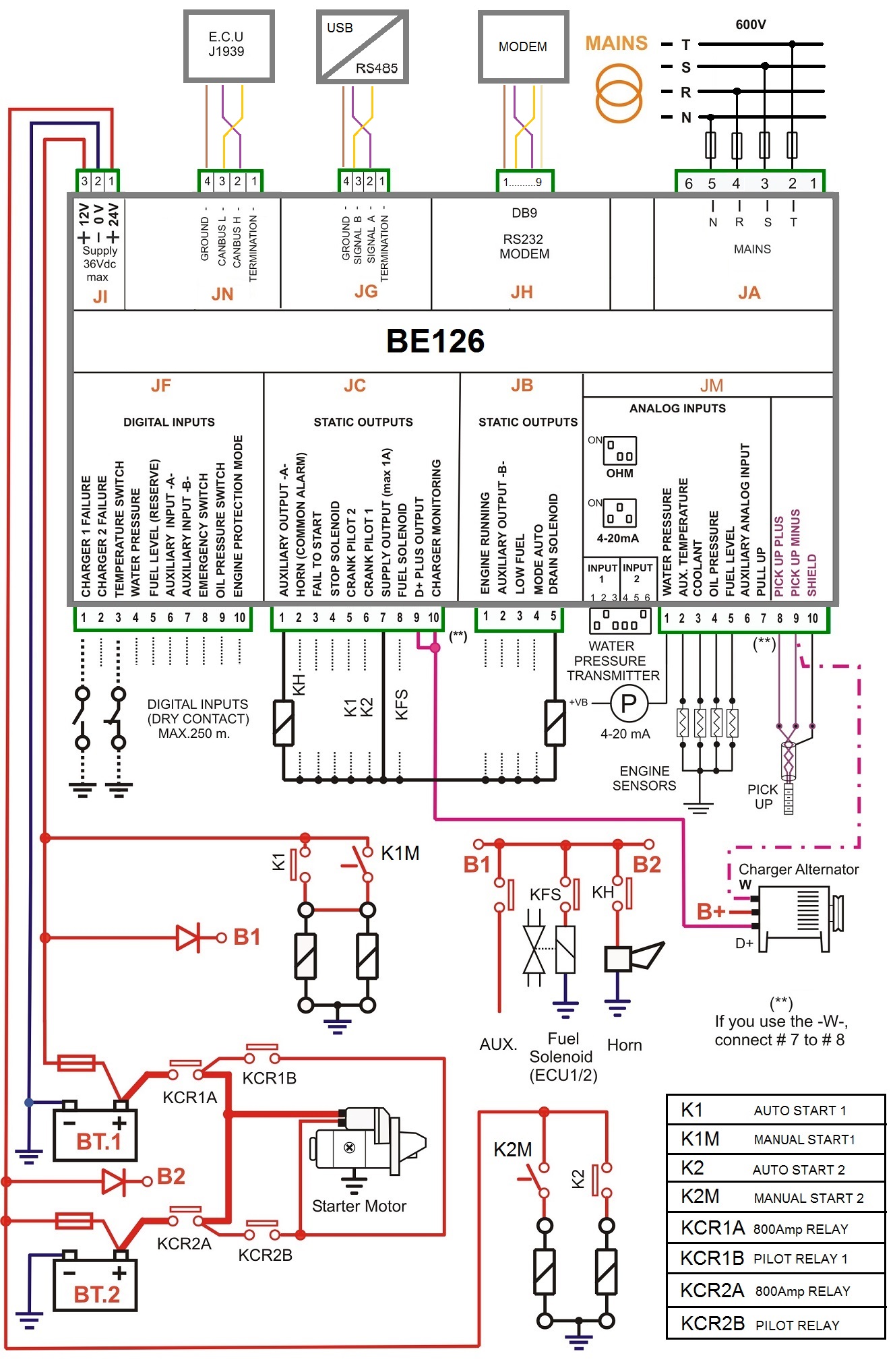
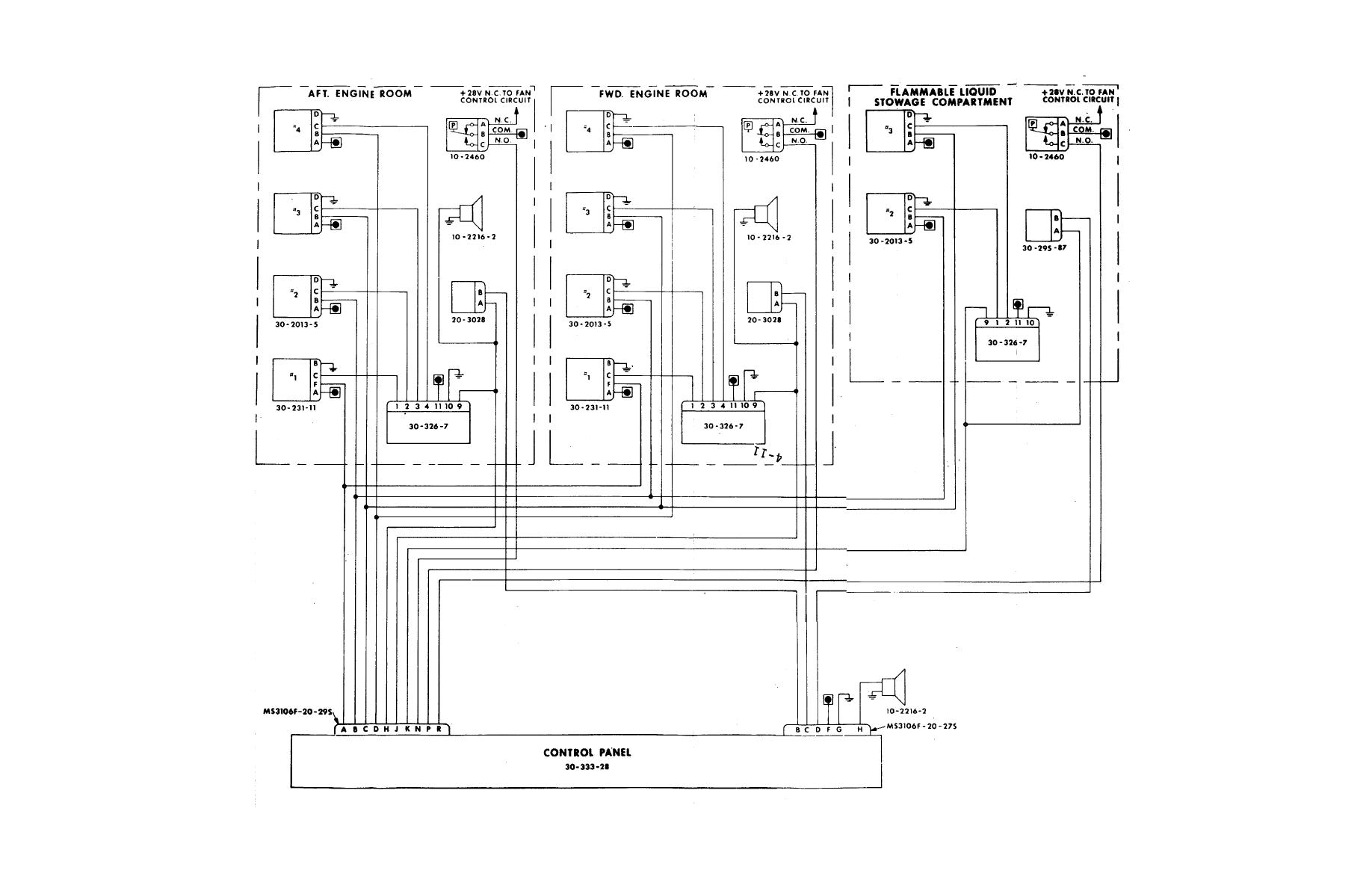
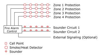
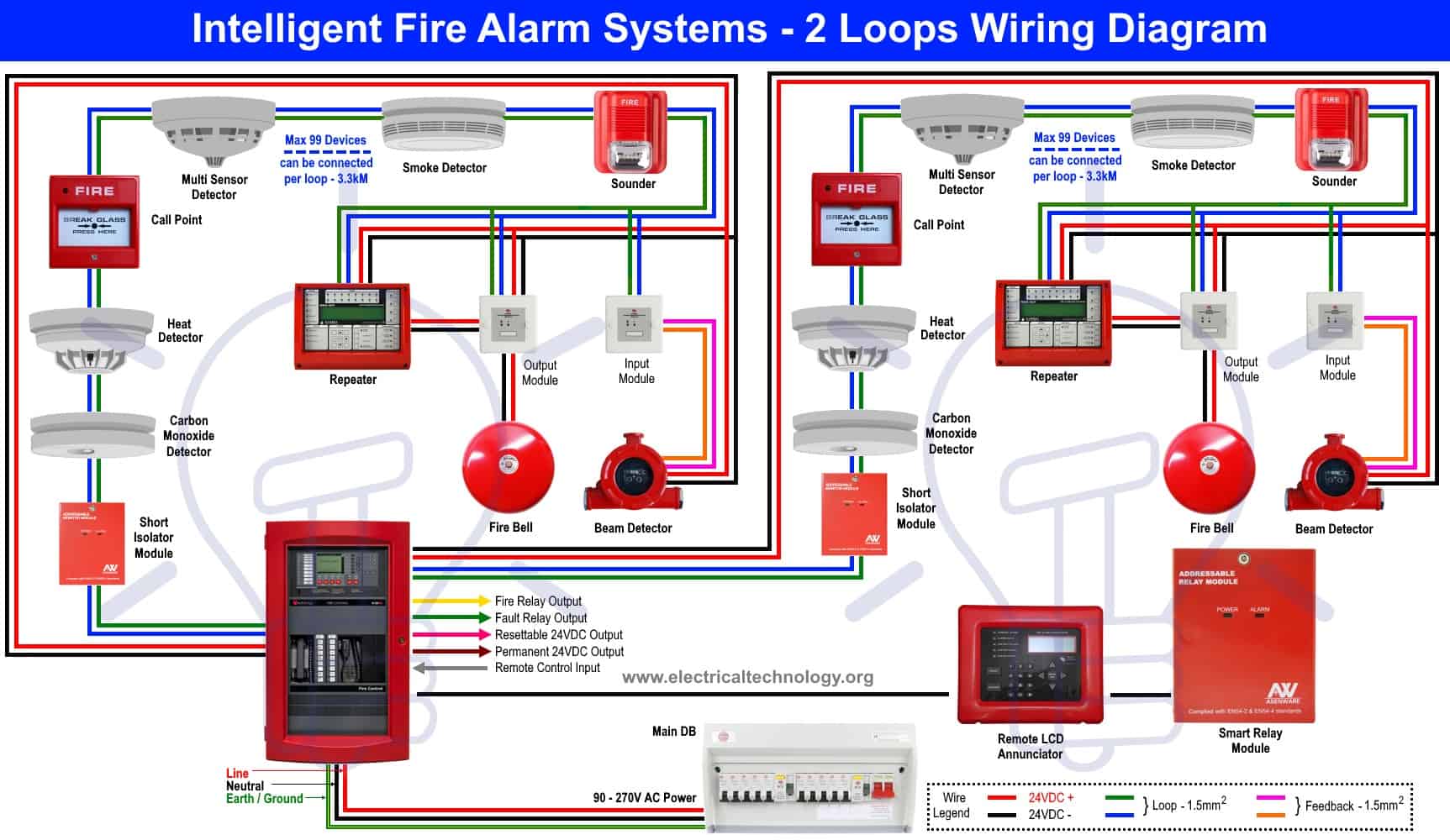
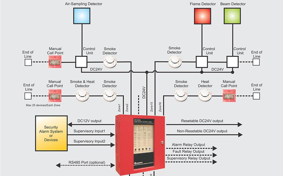
Mega3 nfpa medical gas notification system figure 23. A master or combination alarm panel can do not connect mega3 mastercombina contain multiple signal input boards. Basic alarm system wiring scheme to see where to connect peripherals on paradox alarm board panel. Variety of fire alarm control panel wiring diagram. The following illustrations show schematics wiring connections riser diagram and wire pull for some commonly used fire alarm circuits. Sample dsc alarm pictures and diagrams of some dsc components for reference.
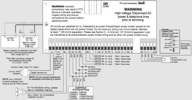
Up to a tion alarm to switchrelay contacts connect maximum of 2 boards or 40. Tamper proof wiring specific information on normally open no vs. Home alarm wiring for a new house. Using the yellow wire makes a yelp noise and the red wire makes a steady tone. This is the basic fire alarm system used in household wiring. How to wire an ids805 816 alarm panel on mygsm unit.
September 23 2018 by larry a. B1x signal board wire routing 236 b1x signal board caution. A wiring diagram is a streamlined standard photographic representation of an electrical circuit. B60 board wire routing figure 24.
Gallery of Alarm Panel Wiring Diagram