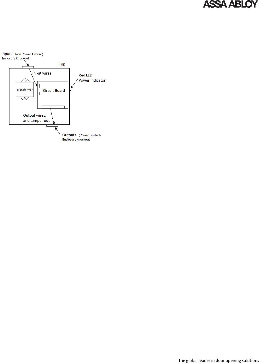
The first initial state delivers a high energy retraction force to the. Mating input power wires are supplied in the install kit.
Corbin Russwin 80 9477 0782 001 02 13 782 Power Controller
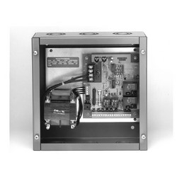
Yale 782 wiring diagram. Wiring diagram single speed. Input power is connected to the power supply via two faston type connectors. The model 7821228 power supply is designed to operate from 12 or 28vdc automotive electrical systems. 120906 5900 x corbin russwin m94 latch retraction. Cub cadet 782 wiring diagram 29092018 29092018 6 comments on cub cadet 782 wiring diagram buy genuine oem cub cadet parts for your cub cadet electrical wiring sn below and ship today. Installation the 782 electric latch retraction controller shall be installed in accordance with the national electrical.
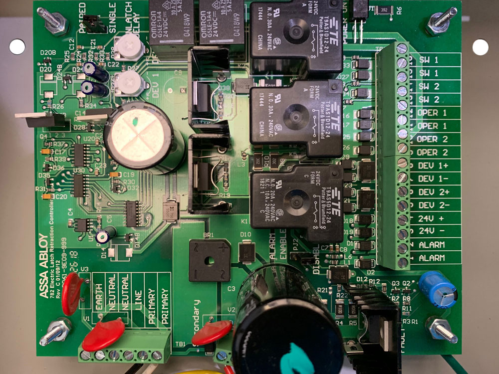
The red wire is positive. 120910 5900 with executive feature. The first initial state delivers a high energy retraction force to the solenoid. Refer to the wiring diagram located on the lid of the controller theory of operation yale 7000p series exit device electric latch retraction or corbin russwin ed4000ed5000 series exit device x m94 latch pullback the 782 operates at two states. Yale commercial parts and service manuals for cylinderskeying exit devices mortise locks. Refer to the wiring diagram located on the lid of the controller theory of operation yale 7000p series exit device electric latch retraction or corbin russwin ed4000ed5000 series exit device x m94 latch pullback the 782 operates at two states.
Lawn garden tractor. 120912 5900 x two 697 touchless plates. 120904 5900 x rf to toggle hold open. The black wire is negative. Page 10 elementary diagram bridge mainline single phase 227982 sht. Refer to the wiring diagram and use 14 awg.
120911 5900 pair using sync cable. 120903 5900 x yale g and b to shunt wall plates. Box 769 muskegon mi 49443 0769 phone. Yale and corbin russwin are assa abloy group brands. The 782 is designed to be used with ul listed yale 7000p series electric latch retraction or corbin russwin ed4000ed5000 x m94 series latch pullback exit devices. Notice motor in accordance with the appropriate crane interconnection wiring diagram as shown in figure 10.
Page 9 wiring diagram two speed elementary diagram 329153 sht. 120907 5900 x sargent 56 with rlm5900. Yaleshaw box standard bridge controls utilize variable frequency drive. Specifications 70 and 74. Yale commercial 782 electric latch retraction controller 120 volt ac 60 hertz 750 milliampere 14 awg. If bridge motors quick connection plugs are not pre wired connect leads on motor cables from the bridge control panel per figure 1.
120905 5900 x yale p latch retraction.
Gallery of Yale 782 Wiring Diagram