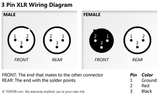
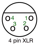
The above diagram shows you the pin numbering for both male and female xlr connectors from the front and the rear view. If the signal source is equipped with an output transformer.
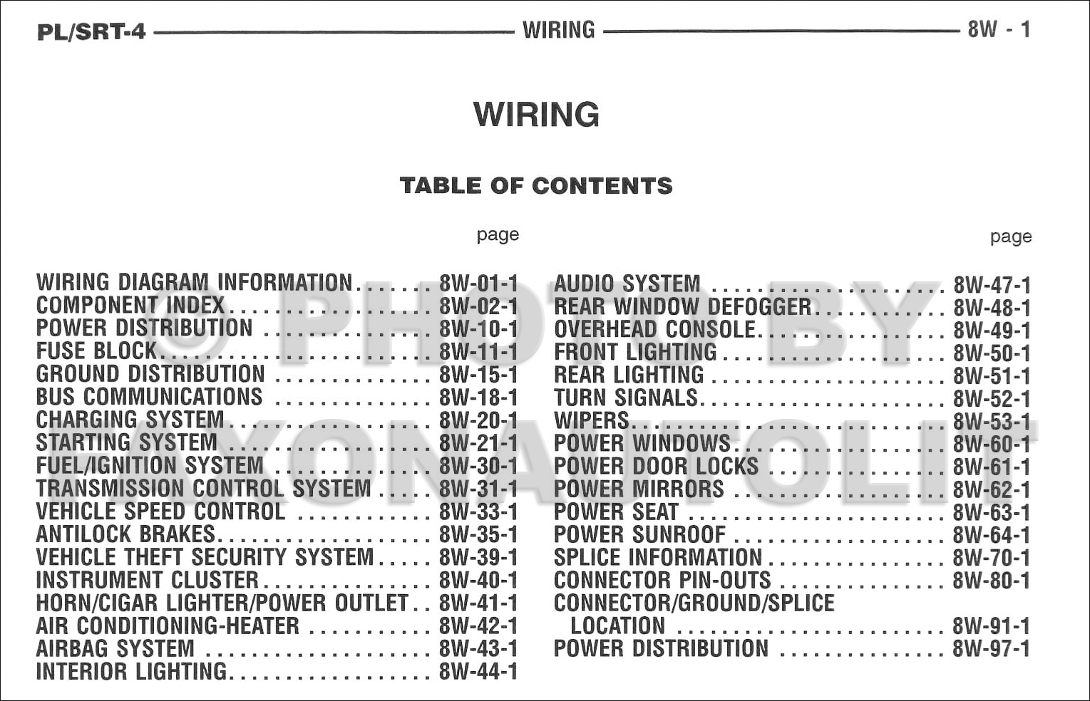
117a 2005 Dodge Neon Wiring Diagram Pdf Wiring Library
Xlr wiring diagram pdf. Find your xlr wiring diagrams here for xlr wiring diagrams and you can print out. The rear view is the end you solder from here are the connections on each pin. Van den hul audio cableconnector wiring diagrams female balanced xlr to male unbalanced rca fig. The usual way to connect a 3 pin xlr to a 14 trs aka stereo jack plug is to use the following pin allocation. If the signal source is equipped with a pseudo balanced output stage. A wiring diagram is a simplified standard photographic depiction of an electric circuit.
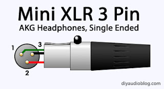
An explanation and diagram showing how to wire an xlr cannon connector to a 14 inch stereo jack connector. Speaker adapter cable 2 wire xlr jack mono pin 1 jack casing. Collection of xlr wiring diagram pdf. 3 pin xlr connectors are standard amongst line level and mic level audio applications. If the signal source is equipped with a cross coupled output stage. Xlr xlr pin 1 pin 1.
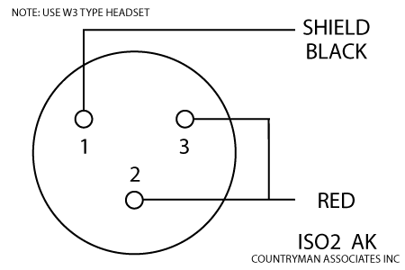
It shows the elements of the circuit as simplified forms and the power and also signal connections between the tools. Search for xlr wiring diagrams here and subscribe to this site xlr wiring diagrams read more. Sommer cable audio cable microphone cable balanced according to iec norm. Speaker adapter cable 2 wire xlr speakon pin 1 1. Life pin 3 1. Ground shield pin 2 pin 2.
3 pin xlr wiring standard. Xlr to 14 trs connector wired for balanced mono. Ground pin 2 1. Xlr to inch stereo jack plug.
Gallery of Xlr Wiring Diagram Pdf