The diagram above shows the general layout of a typical wye. Collection of wye start delta run motor wiring diagram.

34ce8 Wye Delta Starter Wiring Diagram Wiring Resources
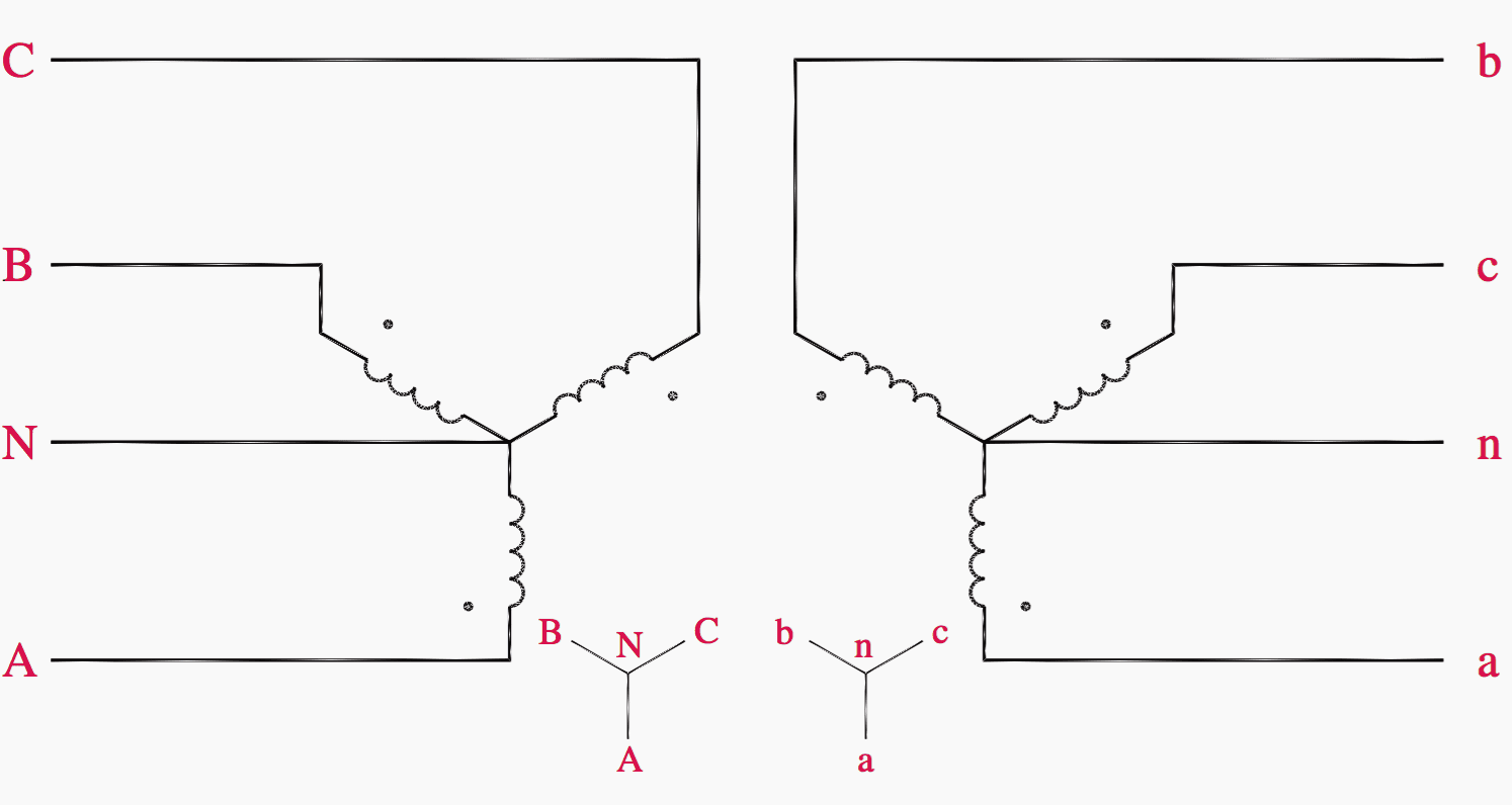
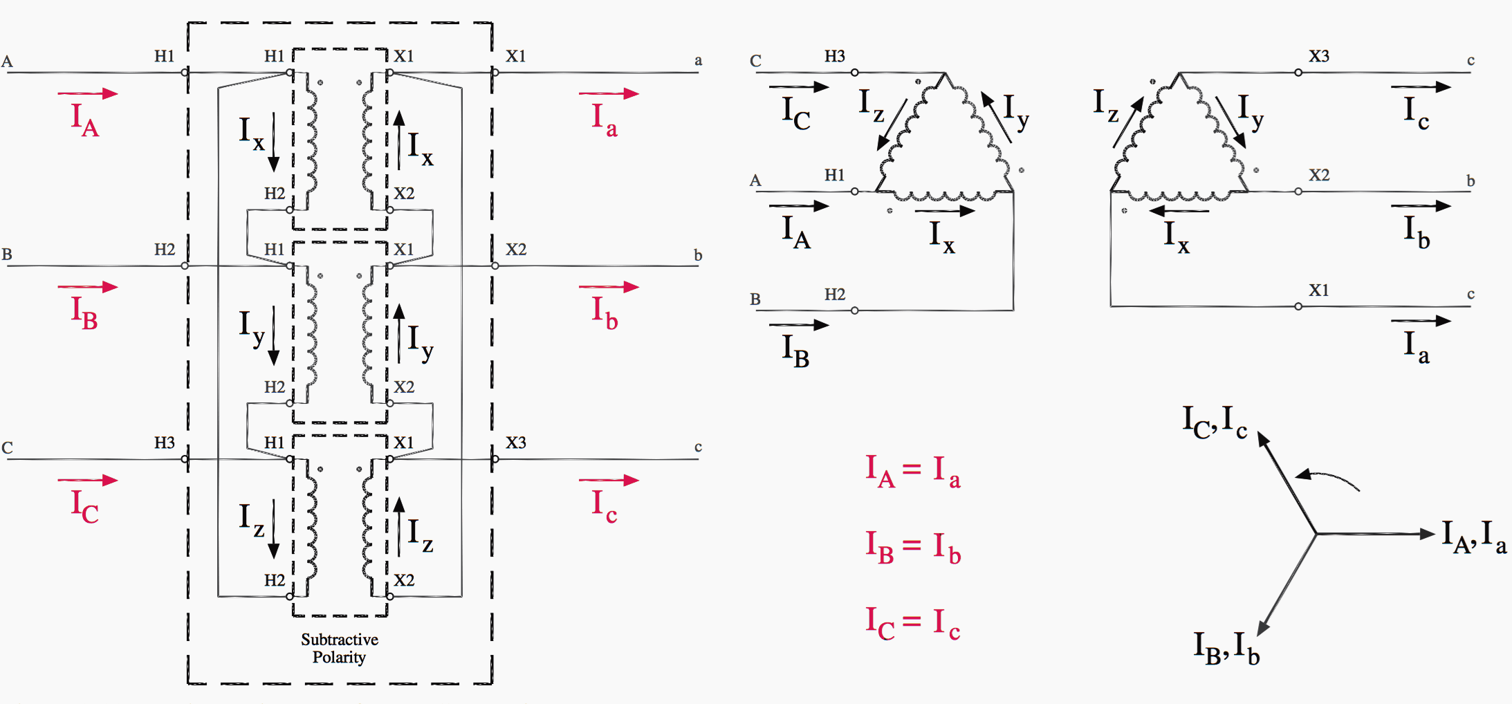
Wye wiring diagram. Single voltage wye or delta with single current transformer. The wye and delta also described as y delta wye delta is a mathematical technique to simplify the analysis of an electrical network. It shows the parts of the circuit as streamlined forms as well as the power as well as signal links between the gadgets. For both wye and delta balanced loads wye and delta equivalent. The primary wye windings are typically grounded. Figure 10 illustrates the wyedelta connection either as three single phase transformers or as a single three phase unit.
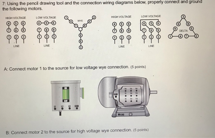
Obtaining from point a to direct b. 6 leads out wye connection single voltage full winding across the line start. Literally a circuit is the course that permits electrical energy. The tail tracks could be extended as much as desired in any direction. In the uk the wye diagram is also known as a star. The objective is the exact same.
The name is given due to the shapes of the circuit diagrams which look respectively like the letter y and the greek capital letter which resembles a triangle. Electrical motors 12 lead dual voltage wye startdelta run both voltages or 6 lead single voltage wye startdelta run motors designed by us motors for wye start delta run may also be used for across the line starting using only the delta connection. 10 and 12 lead high wye available voltages iso standard 10 lead generators are identical to 12 lead generators with the exception that u6 v6 and w6 are permanently bonded together as n 480v connections shown in blue 416v connections shown in red. Motor wiring diagram us. 6 lead 173 to 1 ratio dual voltage or wye start delta. Wye connection dual voltage with thermal protector.
Delta and wye 3 phase circuits. A first look at a circuit layout could be confusing yet if you can check out a subway map you could check out schematics. A wiring diagram is a simplified conventional photographic depiction of an electrical circuit. Consequently in wye configuration the phase current and line current are equal while in delta configuration phase current is line current divided by 1732. Wye connection with neutral single voltage. Typical 3 phase wiring diagrams and equations for resistive heaters definitions.
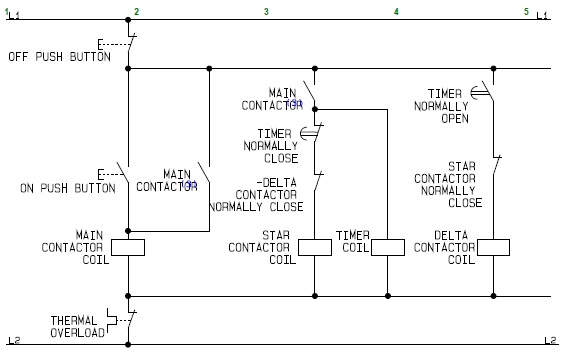
I found this article on the web which is really helpful to understand. In addition to the track arrangement notice the two red marks near the top switch. V p phase voltage v l line voltage i p phase current i l line current r r1 r2 r3 resistance of each branch w wattage w delta 3 w wye. Wye start delta run motor wiring diagram a newbie s overview to circuit diagrams. These mark the location of insulated joints that will be required for two rail dc or dcc operation to prevent a short. If the secondary is a four wire delta the fourth wire originating at a center tap on one of the legs of the delta is grounded.
Gallery of Wye Wiring Diagram