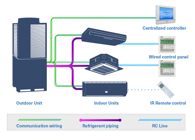
How to wire an air conditioner for control 5 wires the diagram below includes the typical control wiring for a conventional central air conditioning systemfurthermore it includes a thermostat a condenser and an air handler with a heat source. A wiring diagram is a simplified traditional pictorial depiction of an electric circuit.
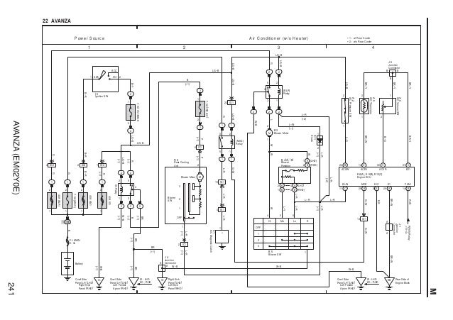
Avanza Wiring Diagram
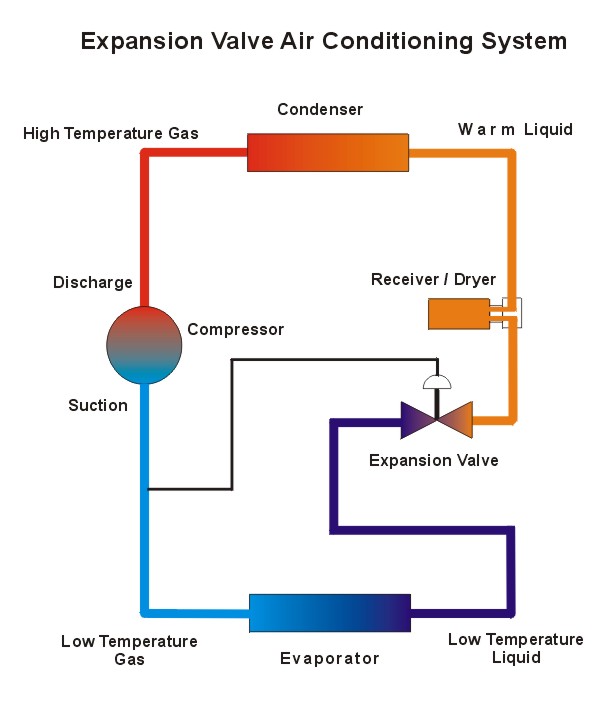
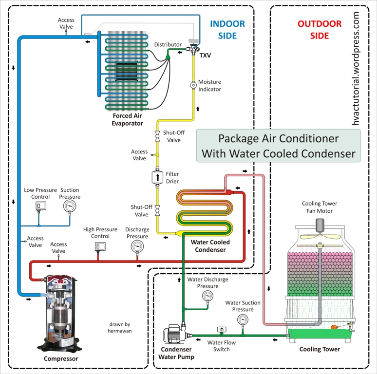
Wiring diagram sistem ac. Moreover the heat source for a basic ac system can include heat strips for electric heat or even a hot water coil inside the. This diagram is to be used as reference for the low voltage control wiring of your heating and ac system. Always refer to your thermostat or equipment installation guides to verify proper wiring. Collection of central air conditioner wiring diagram. The intention of the overall schematic is to show how the circuit functions not how it actually looks. A typical schematic of a packaged air conditioner is shown in fig3.
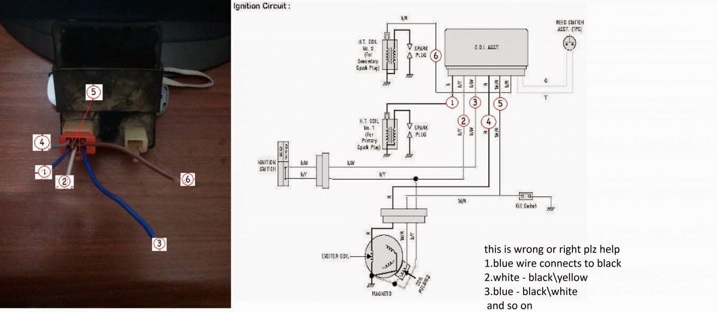
Notesome ac systems will have a blue wire with a pink stripe in place of the yellow or y wire. In electrical schematics the symbols stand for various components in the circuit and the lines stand for the wires connecting them. Air conditioning ac contactor control board 1 this diagram is to be used as reference for the low voltage control wiring of your heating and ac system. I demonstrate how easy it is to use the wiring diagram to figure out where the wires go. Notesome ac systems will have a blue wire with a pink stripe in place of the yellow or y wire. It shows the components of the circuit as simplified shapes and the power and signal connections between the devices.
Always refer to your thermostat or equipment installation guides to verify proper wiring. This diagram is to be used as reference for the low voltage control wiring of your heating and ac system.
Gallery of Wiring Diagram Sistem Ac