However the diagram is a simplified version of the structure. Wiring an alternator.
Delco Remy Regulator Wiring Diagram Motor Selection
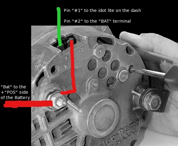
Wiring diagram for delco remy alternator. Replacing a 27si alternator with a 21si alternator. This particular model 10si used in the 1970s and early 80s is the one youll find on the generation of gm cars most often used in demolition derbies. Retrofitting old stlye delco remy regulator to new style delco remy 50vr regulator. A very first look at a circuit diagram might be complex however if you can check out a subway map you can read schematics. Securely crimp and solder the connections. Plug the alternator connector in the receptacle on the alternator.
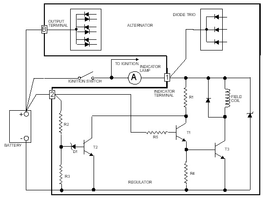
Delco 3 wire alternator wiring diagram 3 wire delco remy 22si alternator wiring diagram and to wiring delco remy. Disconnect the battery negative terminal. Replacing delco remy 10si 11si 12si or bosch k1 alternators with 11si alternator. Battery terminal on the alternator to lower the output voltage for 34si 35si 36si alternators. Voltage can be reduced by installing a jumper. Delco alternator wiring diagram daytonva150 delco remy alternator wiring diagram the diagram provides visual representation of an electric structure.
With key on power is then transferred through the no charge indicator light to the 1 spade on the alternator regulator connection. Between those years you may have the cs 130 or the cs 130d alternator. This diagram shows how to wire a delco gm internally regulated 3 wire alternator. The wiring hookup is the same for the cs 130 and cs 130d alternators. Wiring instructions for the gm delco remy internally regulated cs130 alternator. Generators with a 30si alternator.
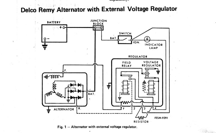
Replacing a 20dn 30dn 41 dn and dc. This makes the process of assembling circuit easier. Connect a length of 10 gauge wire to the output stud on the back of the alternator using a solderless ring. This diagram shows the simple wiring diagram for negative ground delco si series alternators the ignition switch is most commonly powered from the starter battery stud but source may vary depending on application. It shows the components of the circuit as simplified shapes and the knack and signal links with the devices. Delco remy alternator wiring diagram 4 wire wiring diagram is a simplified agreeable pictorial representation of an electrical circuit.
How to wire an ac delco 3 wire alternator step 1. The gm delco remy cs130 alternator was used on gm vehicles from about 1986 1996. 1995 1998 was a transitional period for the cs 130. On both the cs 130 and cs 130d alternators must have a resisted ignition wire to the l terminal. Splice a 14. Typical wiring diagram lower output voltage.
Delco 3 wire alternator wiring diagram a novice s overview to circuit diagrams. If necessary use an 18 awg minimum wire size terminated with ring terminals to fit remote sense and battery b.
Gallery of Wiring Diagram For Delco Remy Alternator