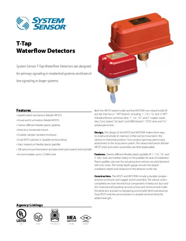
10 amps at 125 or 250 vac60 hz 050 amps at 125 vdc 025 amps at 250 vdc 3. Switch and wiring 1.
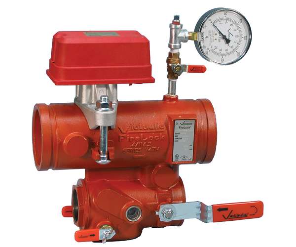
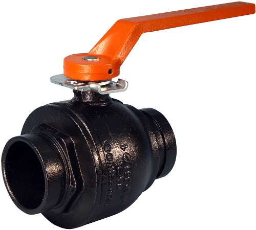
Victaulic Series 747m Firelock Commercial Zone Control
Victaulic tamper switch wiring diagram. Switches supervise the valve in the open position. 10 amps at 125 or 250 vac60 hz 050 amps at 125 vdc 025 amps at 250 vdc 3. The supervisory switch contains two single pole double throw pre wired switches. Re wire the gear operator. Firelock ball valve series 728 installation wiring and gear operator replacement instructions i 728 i 728 for complete contact information visit. The pdrp 2001 facp has four programmable nac outputs or releasing solenoids and three programmable form c relays.
120 vac 60 hz 366 amps 240 vac 50hz 2085 amps pdrp2001e. One switch has two 18 insulated wires per terminal which permit complete. One switch has two 18 mtw wires per terminal which permit. 2 wire or 4 wire pull stations waterflow devices tamper switches and other normally open contact devices. Switch and wiring 1. 10 amps at 125 or 250 vac60 zh 050 amps at 125 vdc 025 amps at 250 vdc 3.
The supervisory switch contains two single pole double throw pre wired switches. Switch and wiring 1. Verify proper valve andswitchfunction. Switches supervise the valve in the closed position. Cycle the valve fully opened and then fully closed. The above diagram shows a connection between the common terminal yellow s1 and yellow with orange stripe s2 and the normally closed terminal blue s1 and blue with orange stripe s2.
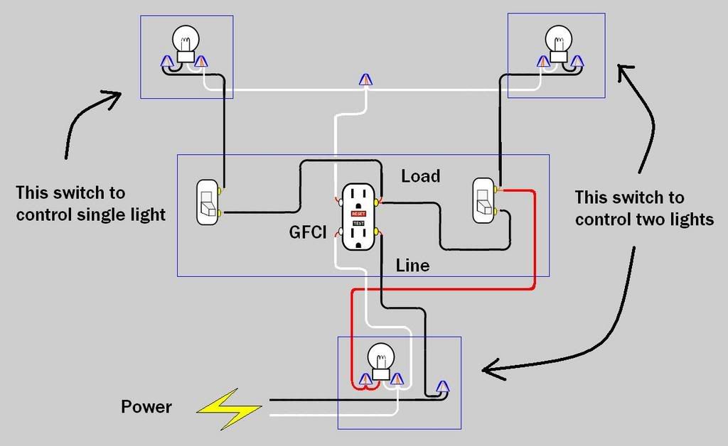
In this example the indicator light and alarm will stay on until the valve is fully open. Refer to the switch and wiring section. One switch has two 18 insulated wires per terminal which permit complete. Switches supervise the valve in the open position. Outlets are split wired so that the top half of the receptacle is live all of the time and the bottom of the receptacle is controlled by the wall switch. The supervisory switch contains two single pole double throw pre wired switches.
Switched receptacle outlet wiring diagram depicting the electrical power feeding into an electrical receptacle box and then going to a switch and to another receptacle.
Gallery of Victaulic Tamper Switch Wiring Diagram