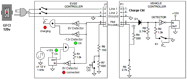
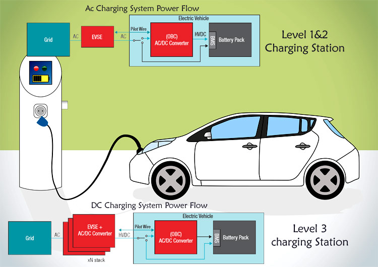
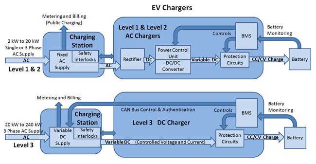
The data link connectors wiring diagrams show the circuits by which the various on board computers exchange information and the diagnostic connectors used for diagnosis and their location. With alternating current ac evse charger electronics within the vehicle invert the ac power supplied by the evse into direct current dc for storage in the battery.
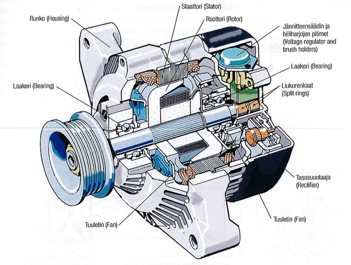
Troubleshooting Alternator And Charging System Problems
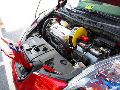
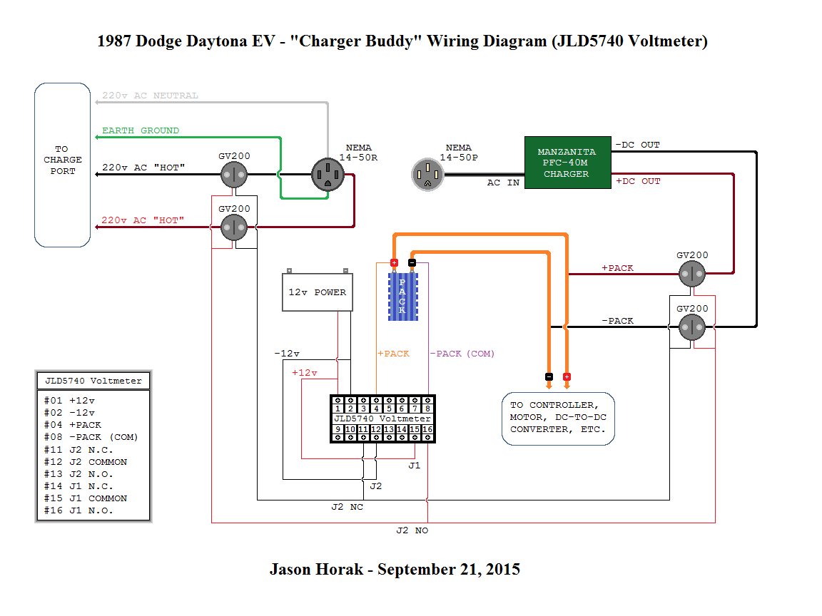
Vehicle charging point wiring diagram. Go to step 4 on page 5 for station mounting instructions. Iet wiring and the regulations circuits for electric vehicle charging points. Circuits for electric vehicle charging points. The red one is to get positive cable with dc ability of 5 volts. The ground distribution wiring diagrams show all vehicle ground points their location and the components common to those ground points. Black cable serves as floor exactly like in any other device.
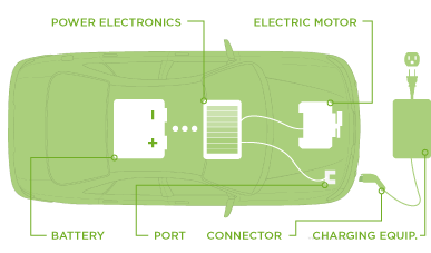
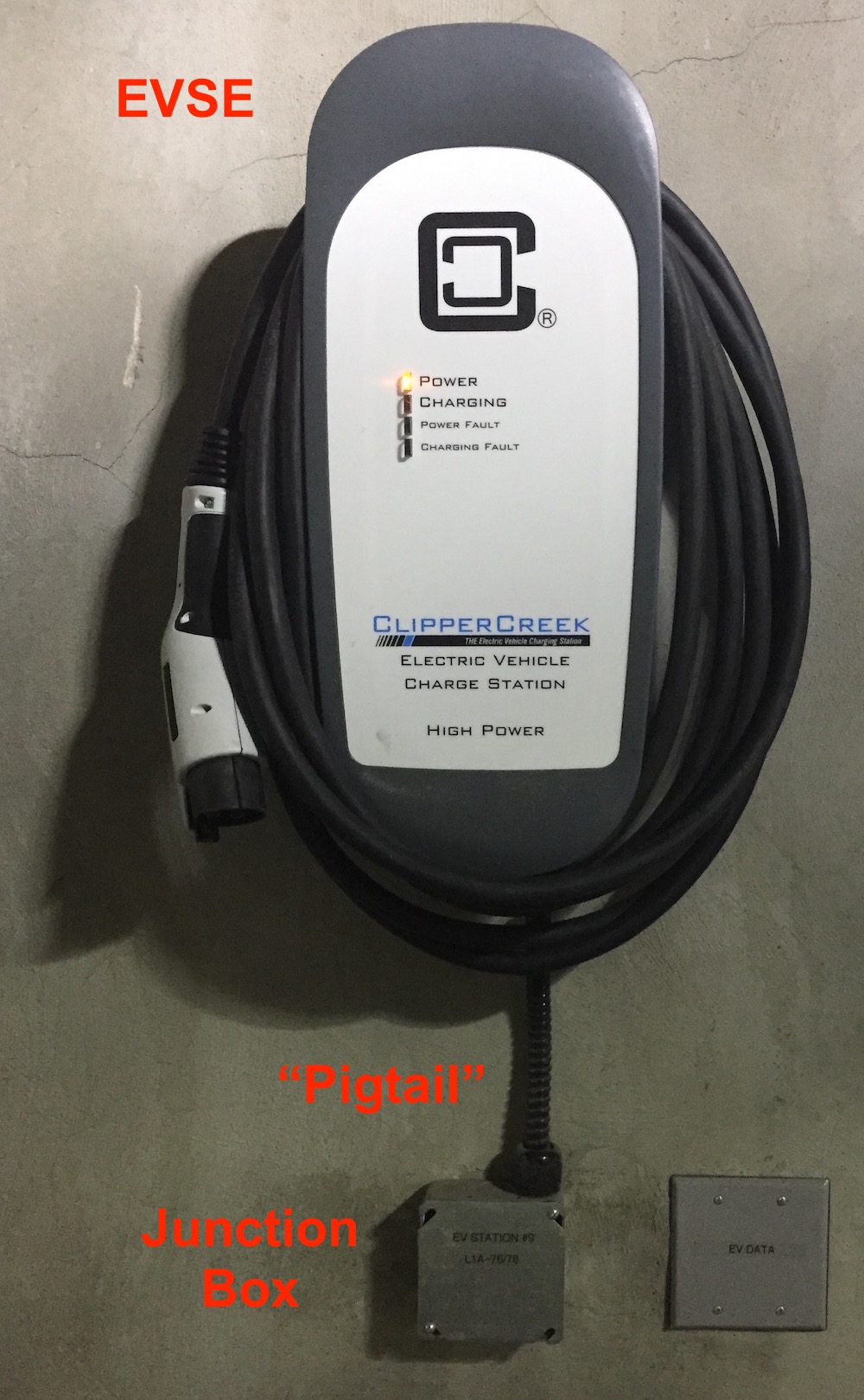
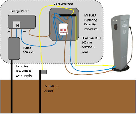
Is a diagram of the overall charging energy flow from the power grid through the evse shaded in orange and into the vehicle through the industry standard j1772 port connector. Is an rcd required at the distribution board to protect a circuit to an electric vehicle charging point if the charging point itself has an rcd fitted. According to car usb charging port wiring diagram you will find just four wires used from the cabletypically it uses black green red and white cable colors. Requires a new two pole circuit breaker tip. Ensure the homeowner has charging cord reaches car without any tautness chosen an installation location that allows the charging cord to reach the cars charging port while still providing slack. Type of socket outlet or connector at an electric vehicle charging point section 722 does not standardise on any one particular type of socket outlet or vehicle connector at charging points but it requires these to be chosen from six different types listed in regulation 722552011.
Gallery of Vehicle Charging Point Wiring Diagram