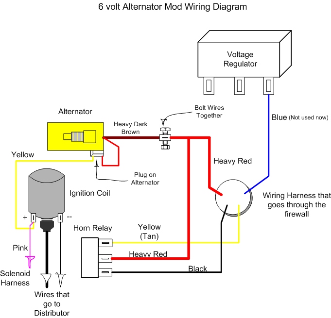
Figure 1 below is a block diagram or a functional diagram of an alternator and its connections to the remainder of the automobile electrical system. The three phase alternator has two parts stator and rotor.

British Car Forum
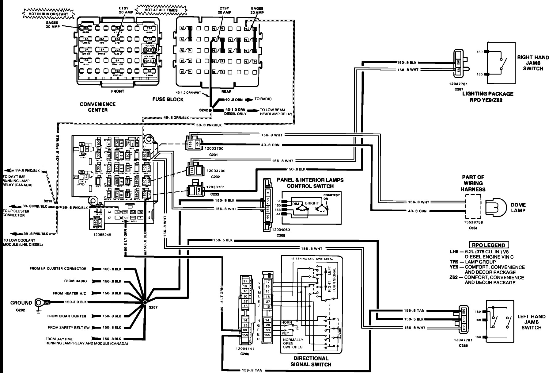
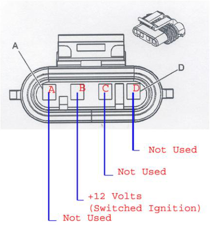
Vehicle alternator wiring diagram. All internally regulated alternators have the same basic electrical connections. By comparing the descriptions below it will be easy to change the instructions to suit the alternator you have chosen. Ford alternator wiring diagram internal regulator. Trailer wiring diagram electrical circuit diagram trailer coupler 4x4 electrical projects electric cars wire vehicle repair car repair wiring a 3 wire alternator with an idiot light great lakes 4x4. It consists of ignition switch fuse panel engine compartment relay box instrument cluster and many more. Take this write up along with the instructions for your particular car to an alternator repair shop and ask the counter.
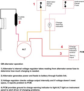
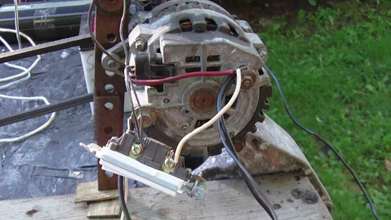
Here the basic internal circuit diagram of the car alternator and the wiring diagram of the alternator with battery is given below. The other terminal is the exciter. The stator contains the three phase armature winding and the rotor contains field winding. Volt alternator and will maintain the battery and accessories on the vehicle. The da plug and wire you installed and connected to the side of coil will tell the alternator to turn on early and will keep your battery charged at idle speeds. Free ford wiring diagrams difference between automatic and manual cars.
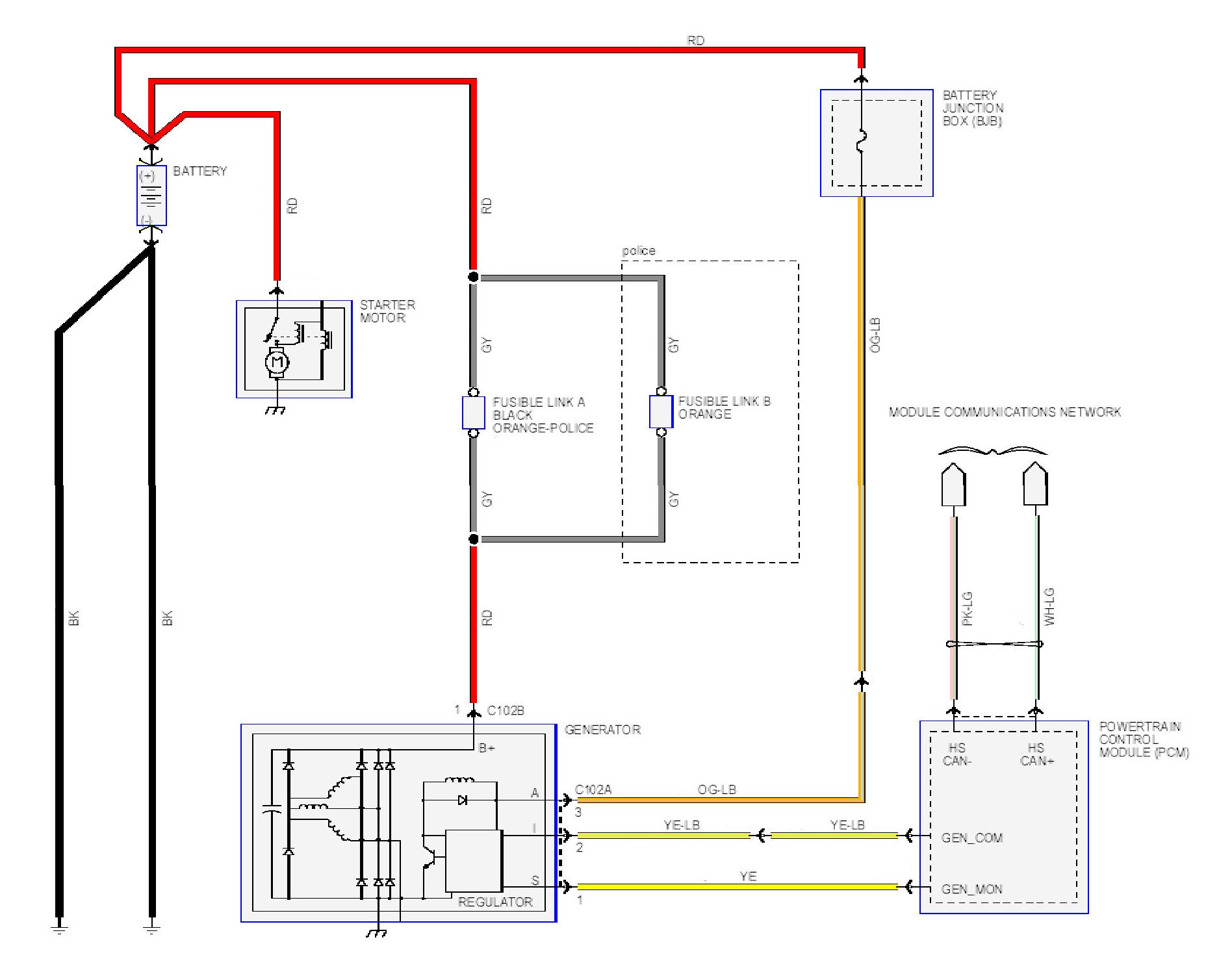
This rotor spins past wire coils causing a magnetic field. How alternator works diy voltage regulator. As you see there are the three phase alternator is used in the car. Because all meters are calibrated dierently you may see a 02v dierence. It requires advanced knowledge to fix an alternator with this diagram. Among all the ford alternator wiring diagrams above this is the most complicated one.
Gallery of Vehicle Alternator Wiring Diagram