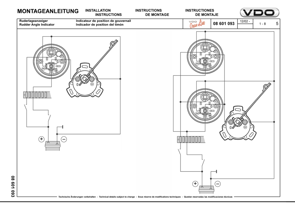
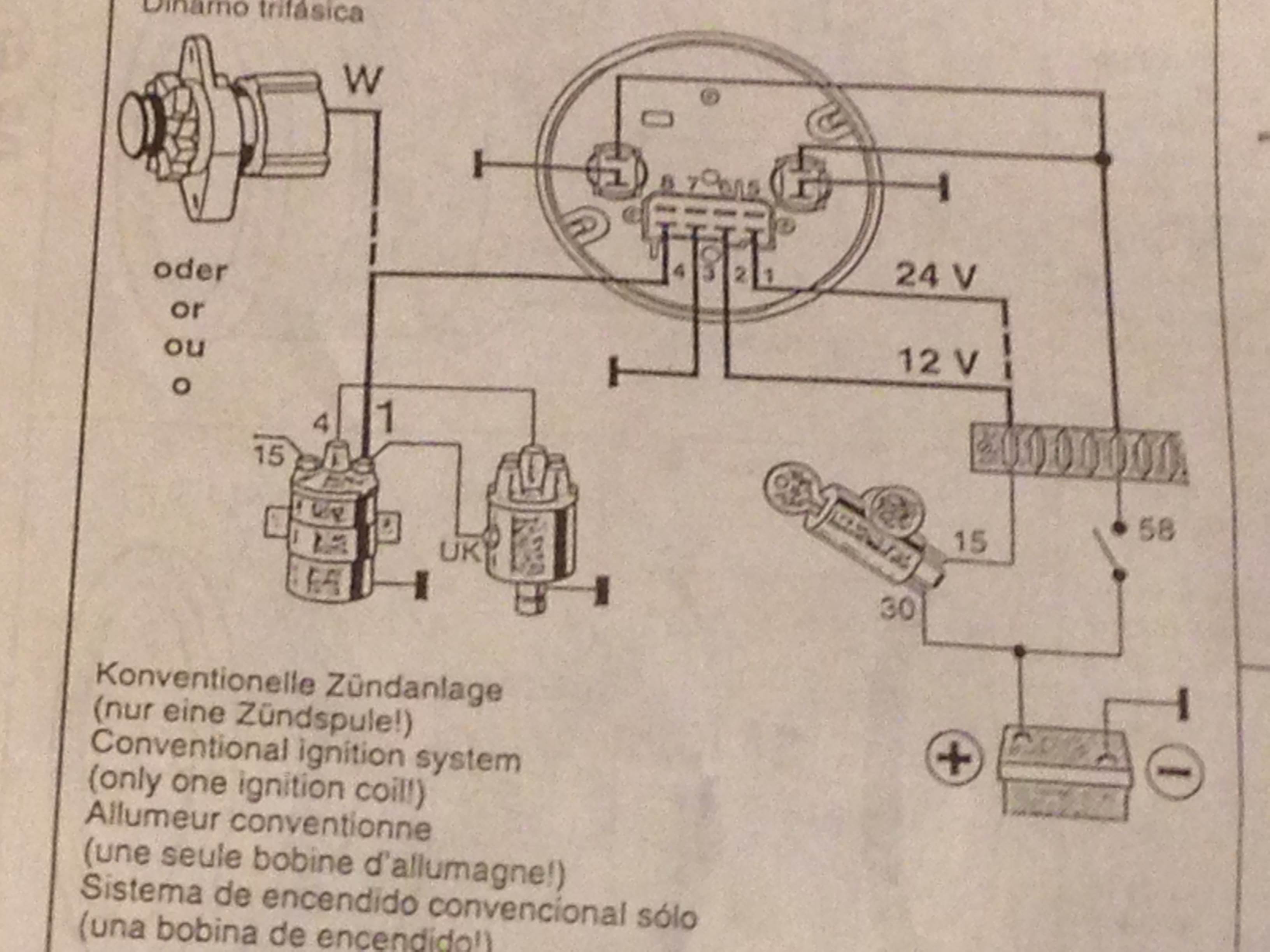
Refer to the wiring diagram diagram g. Installation instructions 1 caution.
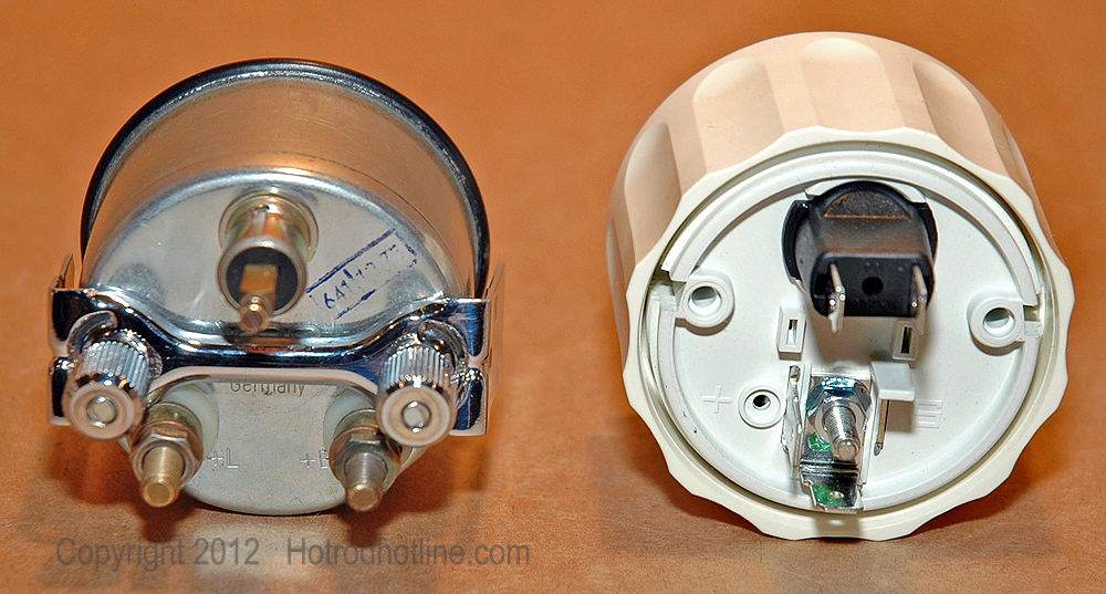
Replacing Old Vdo Temp Gauge With New Vdo Temp Gauge Wiring
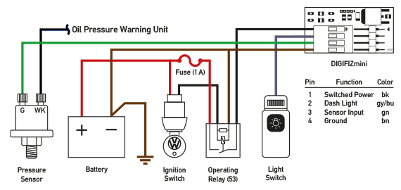
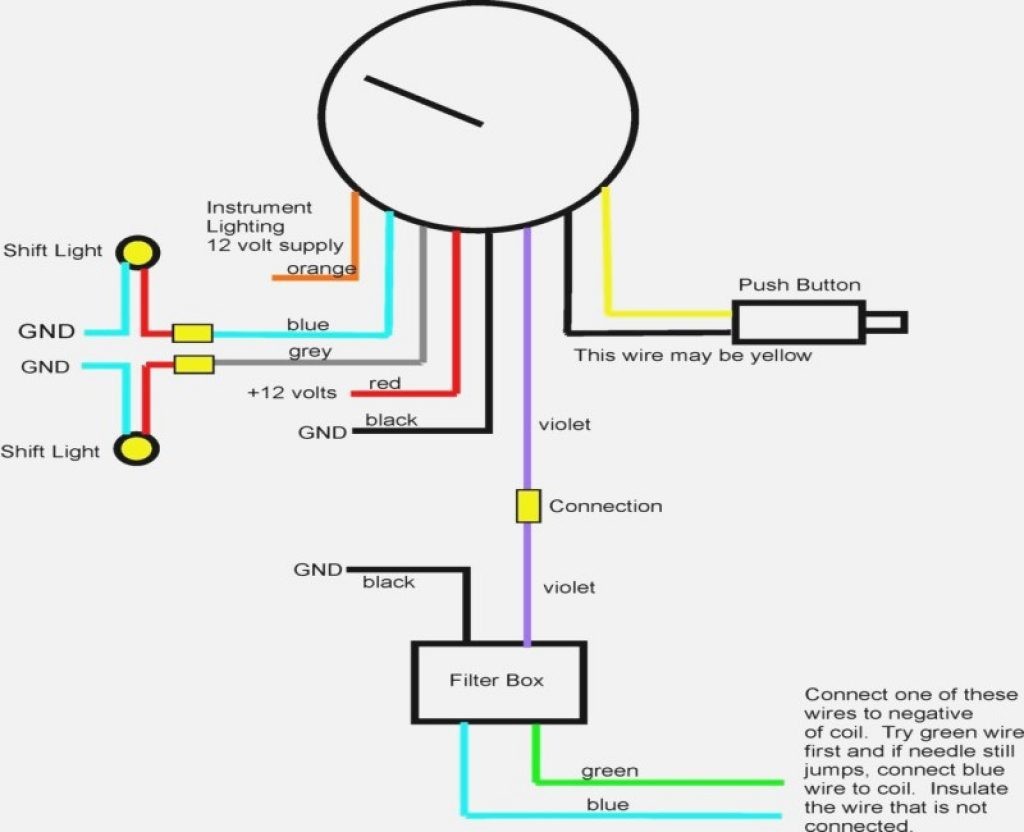
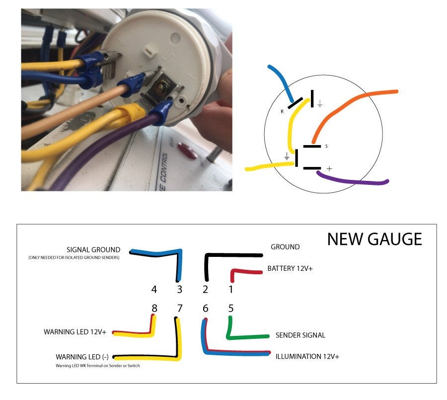
Vdo wiring diagram. Vdo spin lok clamp or mounting bracket 1 5. Assembly or wiring instructions. Light bulb 12 volt ge. Car radio wire diagram stereo wiring diagram gm radio wiring diagram. Always disconnect battery ground before making any electrical connections. Only connect cables according to the electrical wiring diagram.
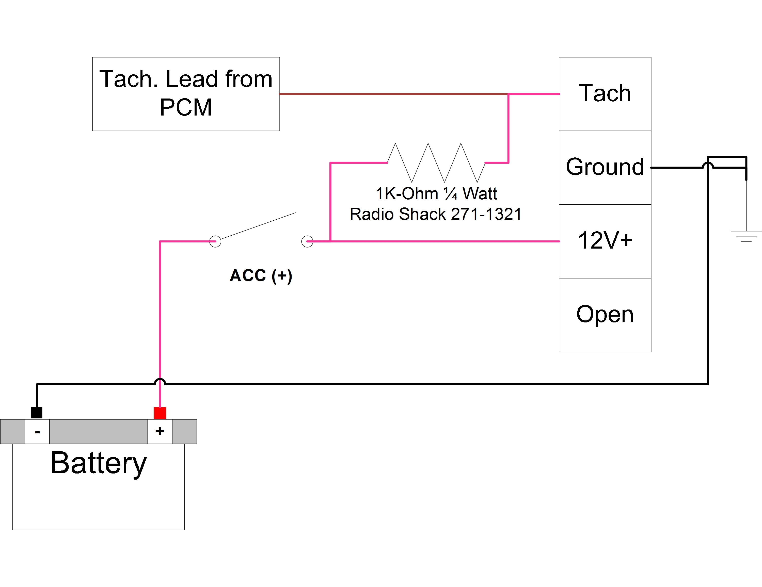
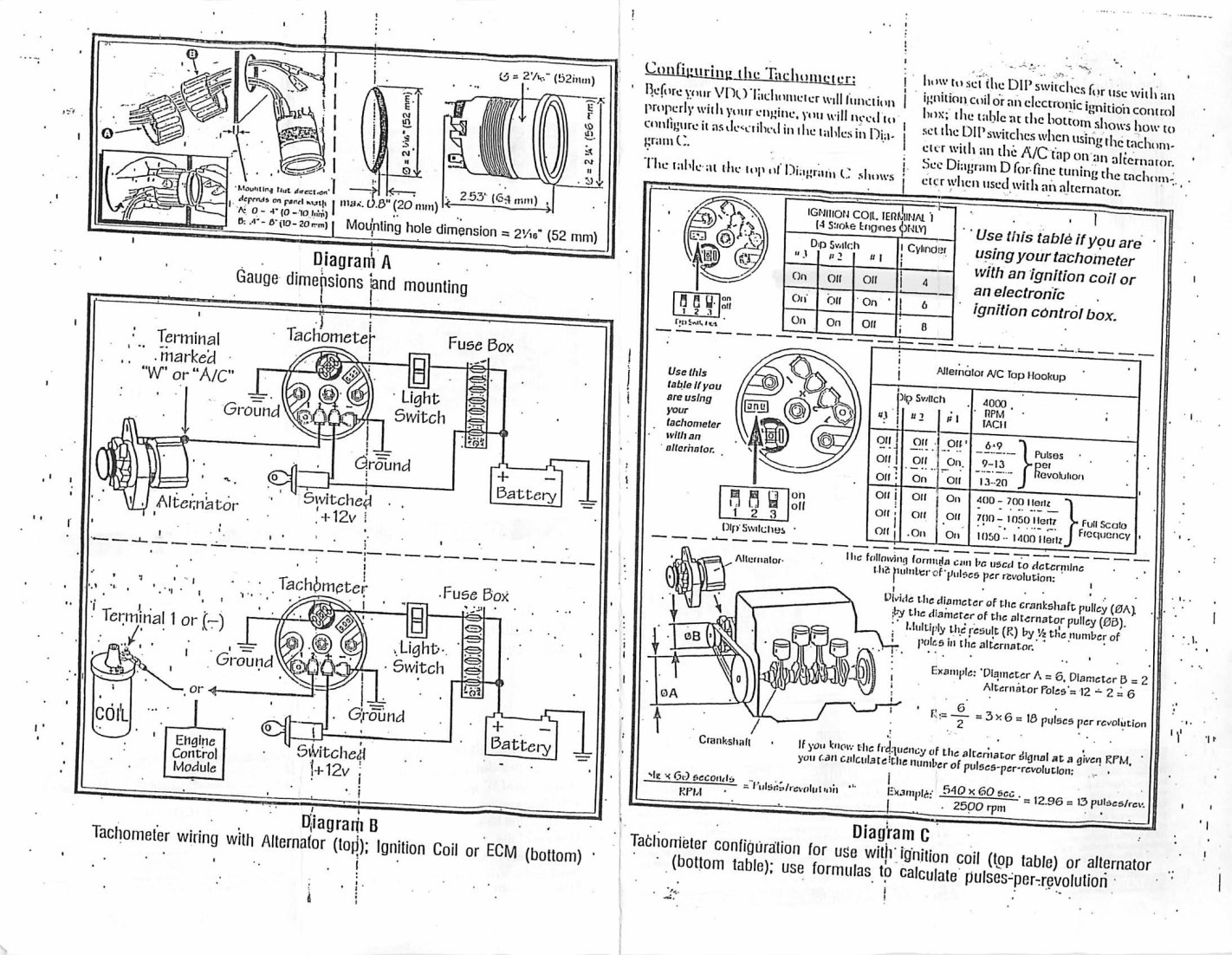
Diagram c shows how to set the switches for diagram d with alternator use this table to calculate pulsesrevolution set switches at this point the installation and wiring of your new vdo programmable tachom the lights in the car and check to see that the instrument and light work properly. 161 or equivalent 2 4. Vdo car radio stereo audio wiring diagram autoradio connector wire installation schematic schema esquema de conexiones stecker konektor connecteur cable shema car stereo harness wire speaker pinout connectors power how to install. 0 electronic speedometer hall effect sender installation instructions and wiring diagram 7udqvplvvlrq type a speedometer 4 wire system 57. Diagram a vdo tachometer with hourmeter is programmable from 5 to 200 pulses per revolution vdo vdo item description quantity 1. The ground œ wire is also run in series including the light socket ground.
Vdo car radio wiring diagrams. Refer to diagram d for the proper wiring of the speedometer. Wire gauges in series from a positive accessory to a source which is not already overloaded with fans air conditioning and such. The final ground run using 14 gauge wire should be connected to a good. Do not deviate from assembly or wiring instructions. Always disconnect the battery ground before making any electrical connections.
Read these instructions thoroughly before making installation. If they dont re check your wiring referring to. If in doubt please contact your dealer or vdo. Junction and attach the wire from the speedometer. Lamp socket push in wedge type 2 3.
Gallery of Vdo Wiring Diagram