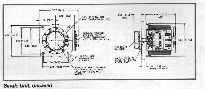
In the tables and diagrams are for motor driven units and units with the knob. The diagram above was photographed off of the data plate on one of my variacs.

A Deluxe Test Bench Variac Nuts Amp Volts Magazine
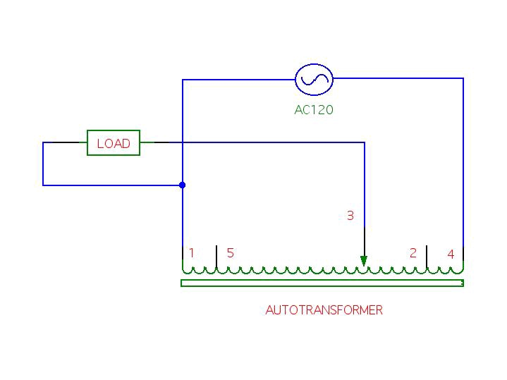
Variac transformer wiring diagram. Portion of variac dataplate showing schematic of device. The function is the exact same. The inductor is shaped like a doughnut toroid with wire wrapped radially this diagram has 5 terminals but 3 and 4 terminal variacs eliminate one or two of. Encountered while drilling holes installing wiring etc during installation. Getting from point a to aim b. A wiring diagram is a simplified conventional photographic depiction of an electric circuit.
A variable voltage autotransformer also known as variac is a transformer which is able to transform variable voltage autotransformer wiring diagram image. On variac transformer wiring diagram. A powerstat variable transformer is a precision product packed with care. It reveals the components of the circuit as simplified shapes as well as the power as well as signal connections in between the devices. Variac transformer wiring diagram a powerstat variable transformer is a precision product packed with care. Variac wiring diagram a novice s overview of circuit diagrams a first check out a circuit representation could be confusing however if you could check out a subway map you can read schematics.
Collection of variac wiring diagram. As you can see there are 4 fixed taps s 1 2 4 and 5 and a moveable tap 3 in a typical application they are wired to allow an input of say 120v and an output of 0 140v. A variable voltage autotransformer also known as variac is a transformer which is able to transform variable voltage autotransformer wiring diagram image. Encountered while drilling holes installing wiring etc during installation. Literally a circuit is the course that allows electricity to flow. August 25 2018 by larry a.
Gallery of Variac Transformer Wiring Diagram