53 connection with two 2 port valves installation instructions for control center vr 65. 4282015 92643 am.

35 Ideas For 2011 Honda Activa Wiring Diagram Stephan Fuchs
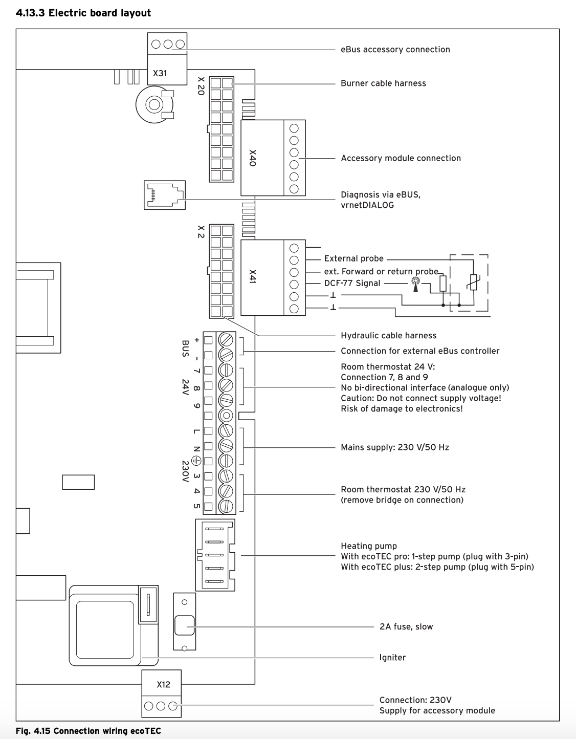
Vaillant vr 70 wiring diagram. Page 1 installation instructions for the competent person installation instructions vrc 7002 vrc 7002 gb ie publishermanufacturer vaillant gmbh berghauser str. Passive cooling assembly circulation fan coil convector wiring tundish air collector heating flow vwl 103 sa outer unit. Add to quote list. Wiring heating flow heating return solar flow solar return heat source flow heat source return cooling flow cooling return. If you would like a quote on this product add it to your quote list and send it to your local branch who will be in touch product information. Vaillant vr70 wiring centre used in conjunction with the vaillant control range.
System diagram 1 vr 70 configuration 3 page 3 system diagram 2 system with boiler. With vaillant unistor use either the cylinder thermostat or the ntc fig. System diagram 8 no vr 70 6 system diagram 8 5. If you cant find what youre looking for please contact us at literature at vaillantcouk and well send the correct document directly to you. 49 21 91 180 fax 49 21 91 1828 10 info at vaillantde wwwvaillantde. Whether youre looking for an installation and service manual or some simple guidance on how to use your boiler we hope youll find what youre looking for in this downloads section.
On orders over 70 ex apply quick turnaround delivered in 1 2 working days search for. Designed to work harmoniously with all current vaillant products the vrc 700 and vrc 700f incorporate weather compensating technology to effortlessly ensure your customers appliances are working to their peak performance to maintain optimum efficiency. Vaillant vr71 wiring centre 20184847 177027. The vrc 700 and vrc 700f system controls allow your customer to take control of their vaillant commercial heating and hot water system. 23260 ex vat 27912 inc vat each. A controller controls and regulates the functions via an ebus.
230 v vrt 360 or vrc 400 cylinder thermostat 230 v note. Vaillant vr 10 temperature sensor. Dhw regulation by vrc 700 system diagram 2 vr 70. 4operating 6 operatinginstructionsmultimatic700002020078200 4143menu ifyoupresstheleft handselectorbuttonmenuyouswitch. Vaillant multimatic 700 system diagrams. Christian trautmann created date.
40 d 42859 remscheid tel.
Gallery of Vaillant Vr 70 Wiring Diagram