Page 1 super ai r flow converter super air flow converterⅡ wiring diagram by model super airflow converter this document describes car models to which the super airflow converter product code. Be sure to perform wiring in accordance with the contents de scribed in the wiring diagram by vehicle model.

Vafc2 Wiring Diagram Diagram Base Website Wiring Diagram
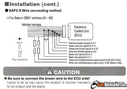
Vafc2 wiring diagram. You can find increasingly more experience as well as understanding how the life is gone through. Honda crx ef civic vafc wiring diagram i know its a long shot but does anybody have the vafc wiring diagram for an obd0 b warning lamp may light up continuously regardless of whether the vafc ii is connected to the ecu and install a plug by referring to the wiring diagram by. Lets take a look at the vafcii wiring diagram to see what sensor wires are left that you must connect. Tee the green wire into the a20 wire on your primary a ecu harness. In addition to wiring diagrams these guides also provide information on alternator identification and procedures for an engine replacement with a new briggs stratton engine that utilizes a different style alternator output connector. S under the hood wiring diagram vafc 2 vortech computer hello all i.
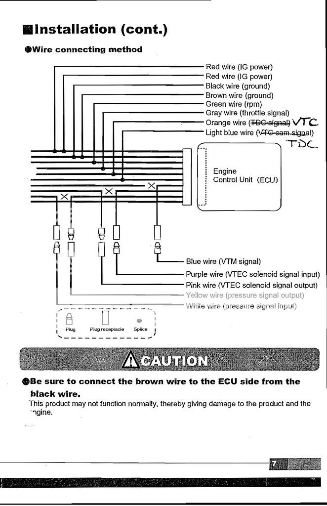
Page 1 vtec air flow converter wiring diagram by model this document describes car models to which the vtec airflow converter ii product code. I recently installed an apexi revspeed meter. 401 a911401 a913 is applicable and ecu terminal arrangement drawings. Afc neo wiring diagram vafc2 wiring diagram wiring diagram afc neo wiring diagram wiring diagram is a simplified tolerable pictorial representation of an electrical circuit. For the operating method and precautions for the vtec airflow converter ii refer to the instruction manual. Incorrect wiring will result in a fire or other accident.
It shows the components of the circuit as simplified shapes and the knack and signal links between the devices. For the operating method and precautions for the super airflow converter refer to the instruction manual. Discussion starter 1 mar 2 2006. 401 a915401 a815 is applicable and ecu terminal arrangement drawings. The vafc2 wiring diagram web content as well as theme of this circuitry diagram really will touch your heart. If any adjustment must be made during actual driving take special care not to interfere with other traffic observing all of the traffic laws and regulations.
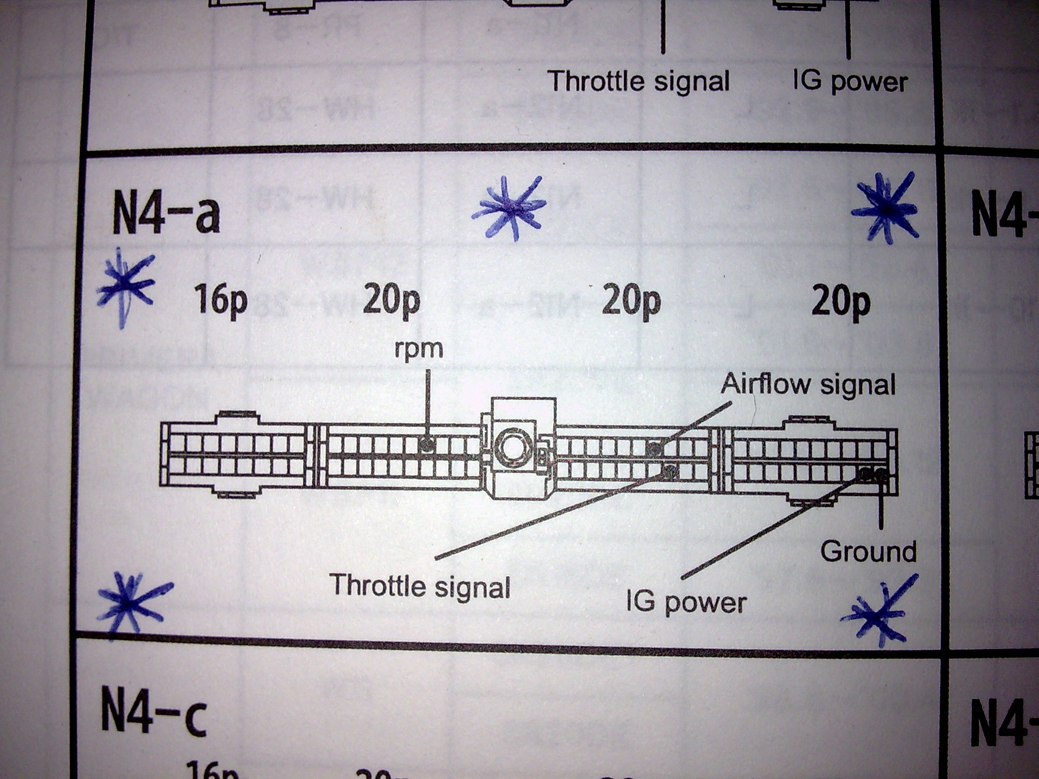
We present vafc2 wiring diagram here due to the fact that it will be so easy for you to access the net solution. 4cut the pressure signal wire or vtec solenoid signal wire of the vehicle harness connected to the ecu and install a plug by referring to the wiring diagram by model. For some applicable models cut the vtm signal wire and install a plug. Joined mar 27 2005 369 posts. 5connect the harness attached to the v afc ii to the plug installed in 4. The vafcii green rpm wire is the next on our list and this wire is the icm or ignition control module which feeds the tach signal to the ecu.
Jump to latest follow 1 7 of 7 posts.
Gallery of Vafc2 Wiring Diagram