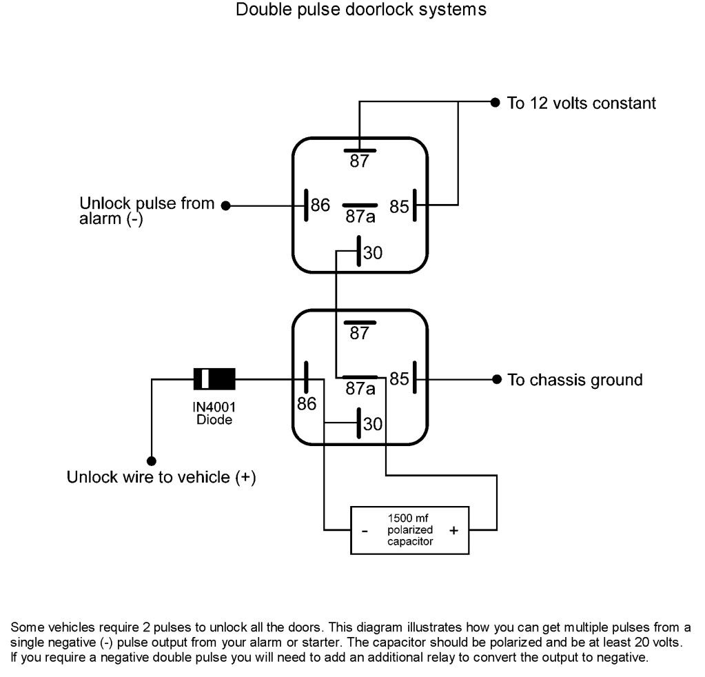
Contacts sr or hr 2 no hr. Mvaj 11 17 21 26 41 and 51 17.

Download Yanmar 1700 Wiring Diagram
Vaa33 relay wiring diagram. Vaa212223 are double pole versions of vaa 111213 respectively vaa 3133 are triple pole versions of vaa 111213 respectively. If you need a relay diagram that is not included in the 76 relay wiring diagrams shown below please search our forums or post a request for a new relay diagram in our relay forum. The relays can be supplied with self or hand reset contacts and changeover contacts. Dozens of the most popular 12v relay wiring diagrams created for our site and members all in one place. Although most relays are labeled at the bottom you can always find the 30 pin set perpendicular to pins 87 and 87a for easy identification to the power source. Wire witha 0 wall insulation black 50 sl notes l.
22 wiring 12 23 preliminary checks 12 24 insulation 12 25 operatereset operation 13 26 restoration of wiring 13 3. It reveals the components of the circuit as simplified shapes and also the power and signal connections in between the tools. Assortment of 12 volt relay wiring diagram. General description vaa relays are voltage operated relays. Auxiliary relays type arevaalstom vaa auxiliary relays are voltage operated relays. Mechanical settings 13 41 general 13 42 contact settings 14.
Auxilliary relays vaa and will withstand an operation of upto 600 per hour. 91 9717005541 011 45631920 91 9717003393. 54 relays fail to economise. Nicnormally closed contacts 2. A wiring diagram is a simplified traditional pictorial depiction of an electrical circuit. If you want a normally open relay you will wire to 87.
The relays are attracted armature units of compact design with positive action and a high degree of mechanical stability. Pos 677 bdz the please state the leiterof issue. Positions viewed from front wiring diagram hand or self reset nor to scale electric co the of 2242 pairs contactsvaaicæoept. The relays are attracted armature units of compact design with positive action and a high degree of mechanical stability. If you want a normally closed relay you will want to wire to 87a. Wiring diagram book a1 15 b1 b2 16 18 b3 a2 b1 b3 15 supply voltage 16 18 l m h 2 levels b2 l1 f u 1 460 v f u 2 l2 l3 gnd h1 h3 h2 h4 f u 3 x1a f u.
Output for a relay. Overload relay 1ct m m motor 3ct to 120 v separate control ot is a switch that opens when an overtemperature condition exists type mfo and mgo only t1 t3 motor 3 2 l2 t2 l3 t3 t2 l1 1 t1 13. 220 250v dc.
Gallery of Vaa33 Relay Wiring Diagram