These 2 wire diagrams fit the needs for most trailers. Typical trailer wiring diagram and schematic.

6 Pin Trailer Connector Wiring Diagram Diagrams
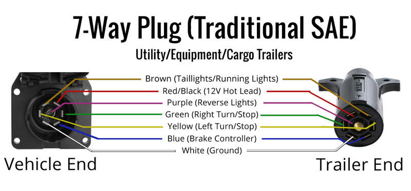
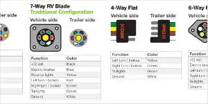
Utility trailer wiring diagram. Extrapolate the same expansion for additional axles. 7 way trailer connectors are used by the following vehicle types. 7 way trailer wiring diagram is explained in details in the picture and the table below. Large 5th wheel trailers. Trailer wiring diagrams trailer wiring connectors various connectors are available from four to seven pins that allow for the transfer of power for the lighting as well as. Complete with a color coded trailer wiring diagram for each plug type this guide walks through various trailer wiring installation solution including custom wiring splice in wiring and replacement wiring.
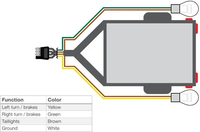
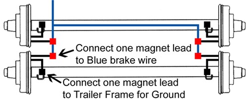
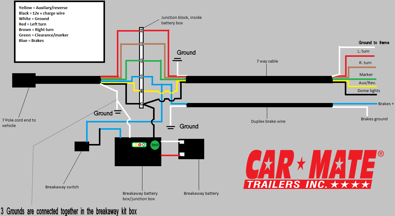
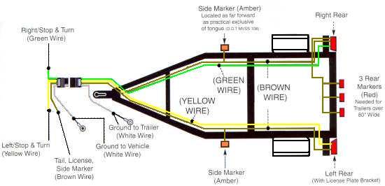
If your vehicle is not equipped with a working trailer wiring harness there are a number of different solutions to provide the perfect fit for your specific vehicle. By law trailer lighting must be connected into the tow vehicles wiring system to provide trailer running lights turn signals and brake lights. The image above shows a single axle trailer and the next image shows wiring for tandem axles. Can also be used as custom wiring on trailers with 3 lightwire systems. The red and blue wire can be used for brake control or auxiliary. 7 pin trailer wiring diagram with brakes.
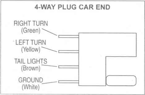
Use on a small motorcycle trailer snowmobile trailer or utility trailer. 34 inch by 1 inch 6 way rectangle connectors right turn signal green left turn signal yellow taillight brown ground white. On most recreational vehicles. The basic purpose remains the same whether your truck and trailer is using a 4 way 5 way 6 way or 7 way connector. Trailer electrical connectors come in a variety of shapes and sizes. Only the blue brake and white ground wires are different.
Among the smaller utility trailers and can easily be adapted to match the larger 5 pole 6 pole and 7 pole.
Gallery of Utility Trailer Wiring Diagram