Universal bolt on turn signal switch wiring youtube size. I had many responses and have collected them in the pages that follow.

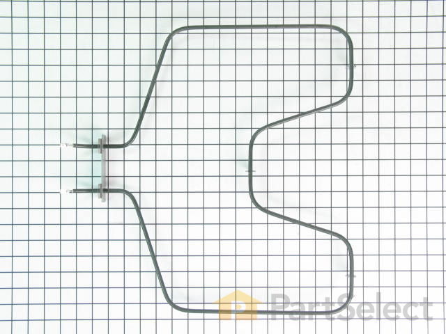
Water Boiler Hot Tea Urn Heating Element For A Burco C10e
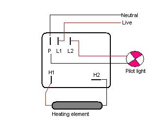
Urn element wiring diagram. I used 12 amp fuses even though the diagram specifies 1 amp. This is why a good diagram is important for wiring your home accurately and according to electrical codes. Urn thermostat 4 pins 20a with manual reset button 140c ksd306x0. And may shorten the element life. Turn signal wiring diagrams recently i asked on fordbarn if anyone had wiring diagrams for the particular turn signal system everlasting that i have mounted on my 29 tudor. Wiring diagrams can be helpful in many ways including illustrated wire colors showing where different elements of your project go using electrical symbols and showing what wire goes where.
1204 form am 301 03 part 090 082 american metal ware midline space saver urns operation and instruction manual for 7000 8000 9000 and chinese tea urn series american metal ware midline and space. Wiring diagram electric catering urn l power indicator green thermostat element inlet supply cable n 1 2 bn bu w bk. In addition i browsed the net and found a few more. The urn is not suitable for heating liquids other than water or for heating water containing. Unfortunately i didnt retain the sources. 1 element 2 element 3 element l1.
800 x 600 px source. Ive included the schematic i used for the 3 wire setup as well as the changes needed to run this from a 4 wire system. Keep your diagram nearby. L9 20r l9 30r 600v ac equip. The switch is included although this can be omitted if desired. Wiring diagrams residential electric water heaters current production 315267 000 time clock switch operates bottom element only to power supply to time clock switch off peak meter operates to power supply to off peak clock 2 wire 1 phase.
3 pole 3 wire 125v250v ac 3ø 250v ac 3ø 480v ac l8 20r l8 30r 480v ac g equip. Wiring diagrams for actual wiring circuit of unit reference circuit type listed on rating plate. The wire which is coloured green and yellow must be connected to the terminal in the plug. Its important to understand exactly how the wiring is going to work. Here are some of the top drawings we obtain from numerous sources we wish these pictures will be useful to you as well as hopefully very pertinent to exactly what you desire about the grote universal turn signal wiring diagram is. Wiring diagram book a1 15 b1 b2 16 18 b3 a2 b1 b3 15 supply voltage 16 18 l m h 2 levels b2 l1 f u 1 460 v f u 2 l2 l3 gnd h1 h3 h2 h4 f u 3 x1a f u 4 f u 5 x2a r power on optional x1 x2115 v 230 v h1 h3 h2 h4 optional connection electrostatically.
Gallery of Urn Element Wiring Diagram