It shows the components of the circuit as simplified shapes and the capacity and signal associates together with the devices. July 30 2018 by larry a.

Universal Oxygen O2 Sensors Bosch Auto Parts
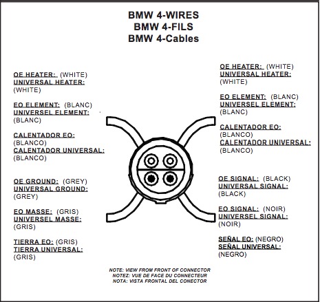
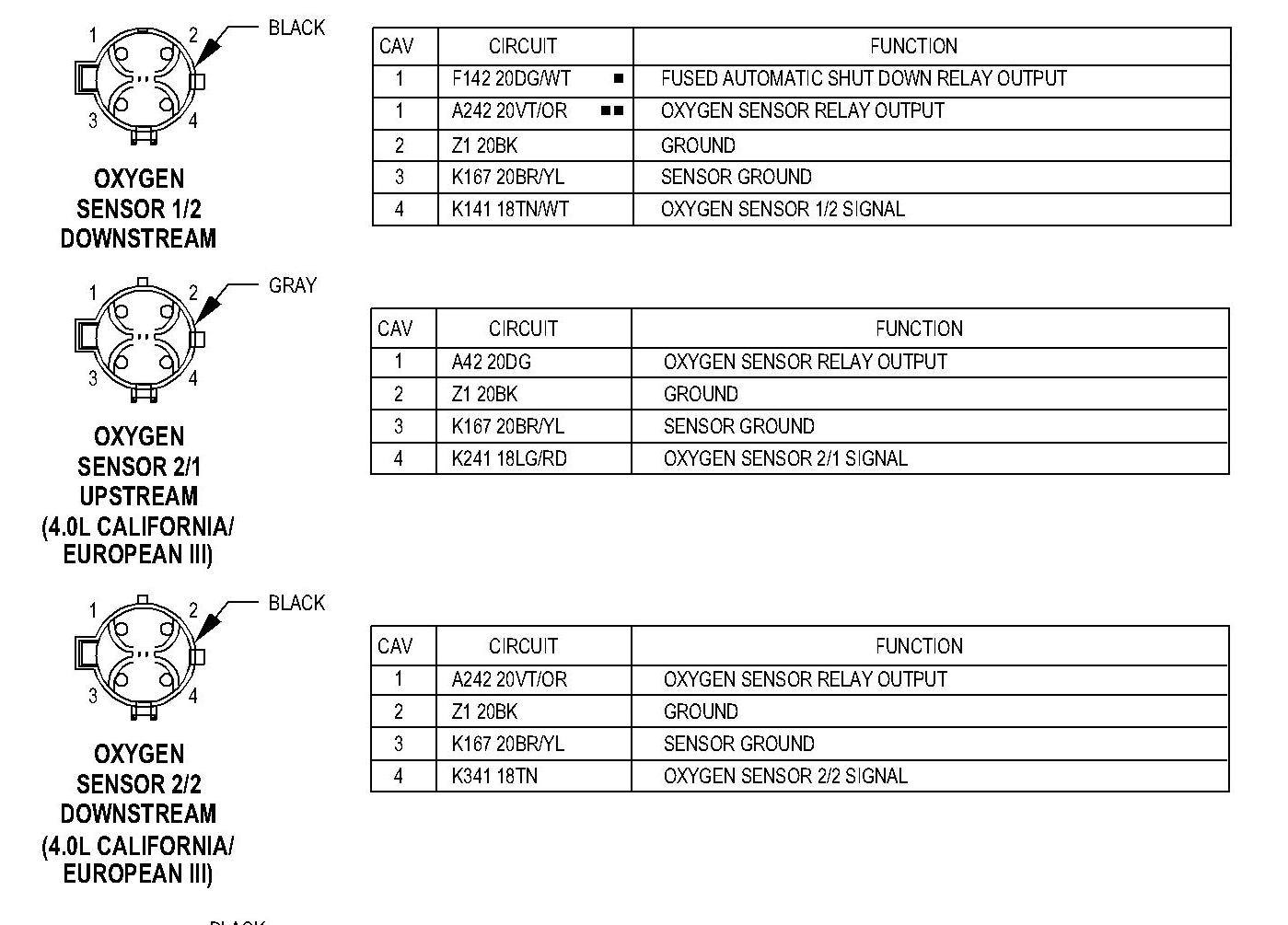
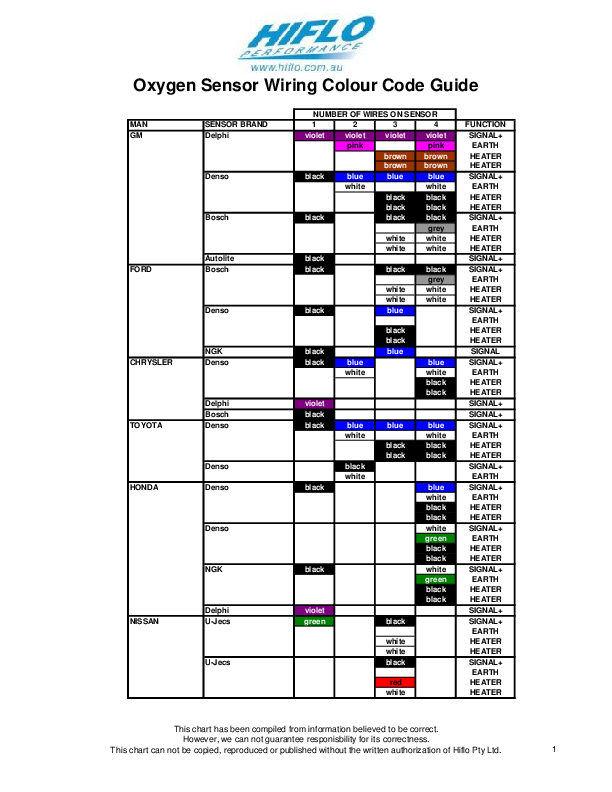
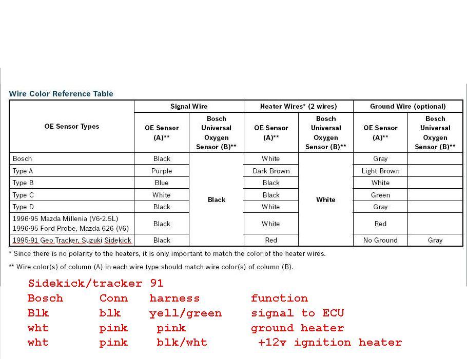
Universal oxygen sensor wiring diagram. Universal oxygen sensor beside the oe sensor and cut the bosch universal oxygen sensor wiring to the length of the oe sensor but do not cut to less than 5 hexflange face to end of sensor wire. Denso oxygen sensor wiring diagram. Learn about the o2 sensor electrical connection and how it relates to the ecm and signal output. This sensor measures the amount of unburned oxygen that is present in the oxygen as it exits the vehicle which is indicative of the fuel mixture. You will need the wiring diagram for the car the oxygen sensor has 4 wires two white which are the heater one positive one negative it doesnt matter which is which the black is ground the gray is the signal wire some have a blue wire black is always ground the blue would be sensor hope this helps. Injunction of two wires is generally indicated by black dot in the junction of two lines.
Universal oxygen sensor wiring diagram wiring diagram is a simplified suitable pictorial representation of an electrical circuit. Honda civic engine diagram. Proceed to step 6. Lay the bosch universal oxygen sensor beside the oe. A wiring diagram is a simplified standard pictorial representation of an electric circuit. Presented here to help you understand the o2 sensor from an electronics and wiring diagram point of.
Cut the old sensor wire to length. Cut the wiring of oe sensor 4 from end of connector as illustrated. Match the cables together. It shows the components of the circuit as simplified forms and also the power as well as signal links in between the devices. I recently installed an obx header purchased through ebay for delivered on my miata including a new single wire o2 sensor. Bosch oxygen sensor wiring diagram.
Strip the wire ends to a length of 7mm. The four wire universal oxygen sensor must be changed approximately every 60000 miles and requires a specific wiring process. Variety of 4 wire oxygen sensor wiring diagram. A wiring diagram is a streamlined standard pictorial depiction of an electrical circuit. But it doesnt imply link between the cables. It reveals the components of the circuit as streamlined forms and also the power as well as signal links between the tools.
Occasionally the wires will cross. 2 options depending on the part number. Wellborn assortment of oxygen sensor wiring diagram. According to previous the lines in a 4 wire oxygen sensor wiring diagram represents wires. Crimp the butt splices with a ratchet crimping tool with red die size 22 16. Although i was not.
This is the place to bosch wideband 5 wire oxygen sensor wiring diagram. Identify the type of denso after market universal fit sensor you need to install thanks to its cable colours.
Gallery of Universal Oxygen Sensor Wiring Diagram