If you do decide to wire up two jacks then you will need to buy an additional jack. Operating cw the way that the ubitx works is a little quirky so it is useful to start by looking at how conventional hf transceivers operate in cw mode.

Digital Modes With The Ubitx Cyberpunk Acres
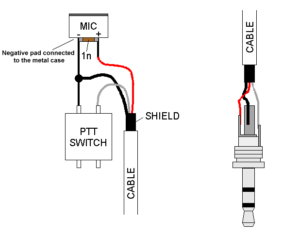
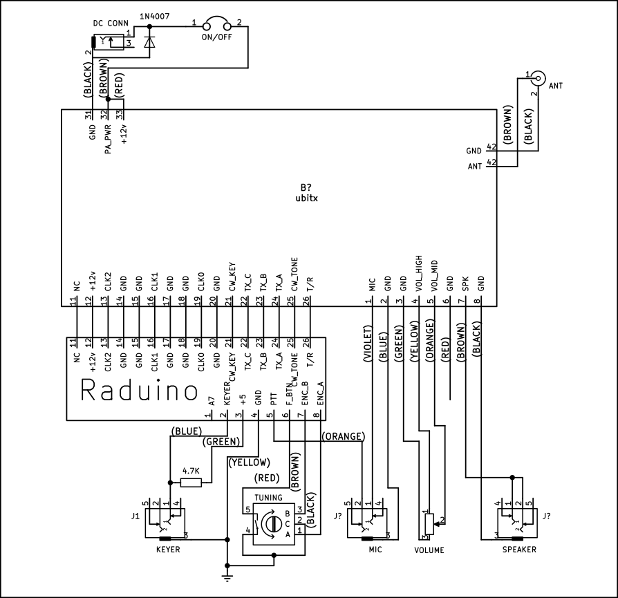
Ubitx wiring diagram. Main board raduino assembly. Wiring diagram ubitx v5 v20. Ubitx wiring to be done. Wiring up the cw key the cw key needs a pull up resistor of 47 k from 5 volts to the key sockets tip. No schematics are known to have been published. For using a dynamic mic a 33uf tantalum.
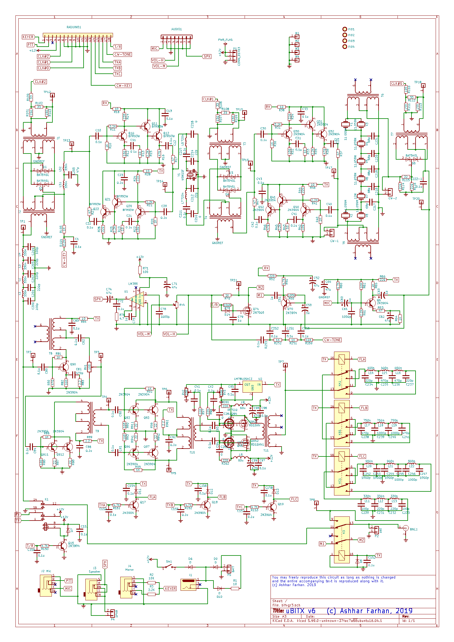
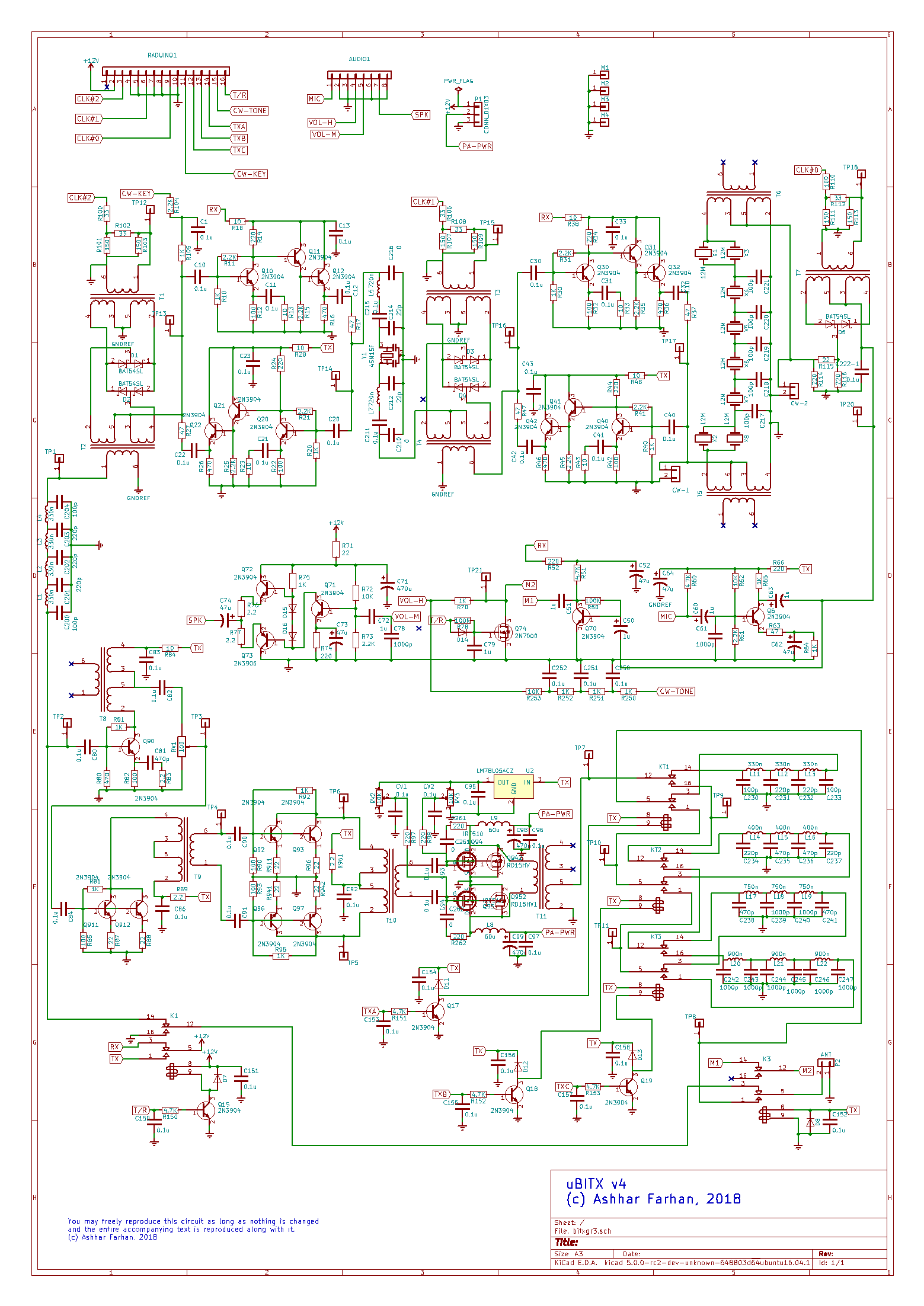
Continuing on with the general receiver concept with lessons learned from the minima the ubitx was published. Download hd pdf file. Original high resolution diagram by w4rjp. The microphone used in the ubitx can be a dynamic one or a condenser type the default mic supplied with ubitx is condenser one. The connections of wiring are as per ubitx schematic if you find volume control function in reverse then switch wires black and red on the 10k potentiometer. Now normally the architecture is explained going from antenna to speaker but i think it is easier to understand if we go from microphone to antenna right to left on the block diagram.
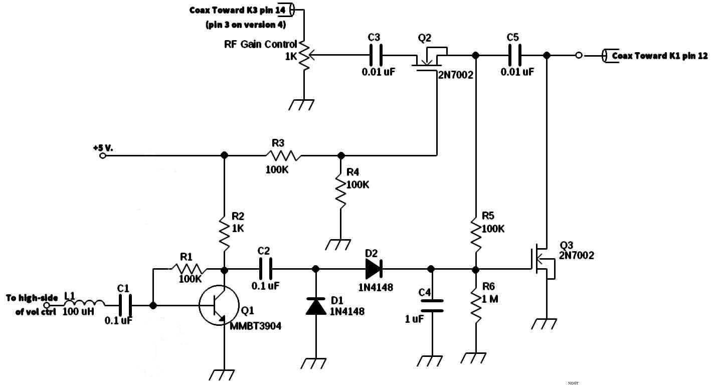
All three resistors 47k pull up for straight key to 5v 22k resistor for dit and 10k resistor for dah will need to be installed. Design of the cw keying. The ubitx is a low power qrp high frequency hf amateur radio transceiver designed by ashar farhan. See circuit diagram below. So lets start with a block diagram of the ubitx. Wiring diagram by w4rjp.
Solder the digital connectors blue wire to the tip tab of the cw key socket. Tx and rx wires for led soldered on ubitx txrx relay. The wiring diagram is shown below. 04 feb building ubitx in nextion case 35 5 inches. Mainboard fuse should be rated 05a not 5a as labeled on the diagram. Construction ubitx case no responses by suniladmin september 7 2018.
For cad files see the ubitx cad files folder. The green wire from the digital connector carries 5v. The blue wire of the digital connector is the keyer line a6 of raduino.
Gallery of Ubitx Wiring Diagram