If a diagram cannot be found within this selection consult customer service. A combination of technical expertise and our distinct customer focus makes us the preferred partner for lighting components lighting management systems and leds.

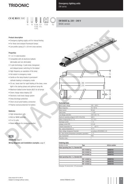
Tridonic Battery Backup Ballast Tridonic
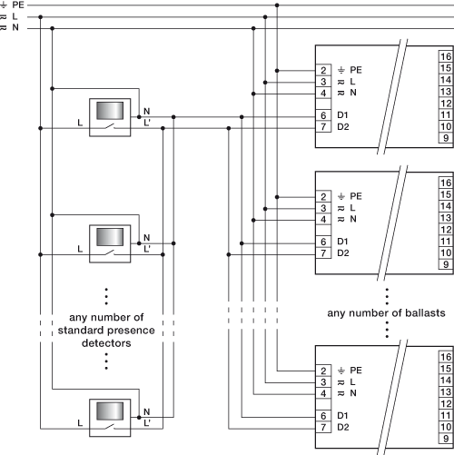
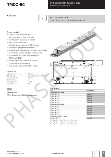
Tridonic emergency ballast wiring diagram. Universal wiring diagram for hf ballasts the following wiring instructions apply to any existing luminaire containing a hf ballast to be converted to 1 hour or 3 hour maintained luminaires depending on model. Certificates data sheets environmental declarations operating instructions etc. Overview of technical documents as pdf grouped according to topics eg. A combination of technical expertise and our distinct customer focus makes us the preferred partner for lighting components lighting management systems and leds. For wiring diagrams and installation examples page 16 em selftest g2 220 240 v selftest version tc f tc dd t5c. Subect to change without notice.
Power control technology ensures maximum emergency ballast lumen factors eblf for all lamps. Ive stripped the light down removed the starters and now im left with the tridonic ballast the bulb sockets a blue wire a brown wire and some mains cable. Our innovative solutions are used worldwide successfully in the lighting industry. Regarding tridonic products in pdf format. Tridonic is a leading manufacturer of lighting components. Tridonic is a leading manufacturer of lighting components.
I know what everything does but i dont want ot make any assumptions as i dont understand wiring diagrams. The diagrams are categorized primarily according to the number of. Subject to change without notice. Ballast emergency ballast relay how to use the emergency ballast wiring guide this document has been customized to contain a wide library of individual dia grams for various installation applications. Wire the lout from the emergency. Emergency lighting use in emergency lighting installations according to en 50172 or for emergency luminaires according to en 61347 2 3 appendix j.
Step 1 remove the switched line from the ballast and wire to the lin terminal of the emergency module. 1 used only in maintained mode because mercury migration may occur during emergency operation. Our innovative solutions are used worldwide successfully in the lighting industry. Here you find operating instructions installation instructions commissioning instructions technical documentation manuals etc. Instant start after mains interruption 05 s intelligent voltage guard intelligent voltage guard is the name of the new electronic monitor from tridonic. Wiring diagrams and installation examples page 14 em basic 230 240 v 5060 hz basic version tc del tc l tc dd tc sel tc tel t5 t8.
Gallery of Tridonic Emergency Ballast Wiring Diagram