Learn the electronics of the engine coolant temperature sensor. Quick fix workaround ford fusion ac evap.

Temperature Sensor Gel 2161 Lenord Bauer Rail Speed
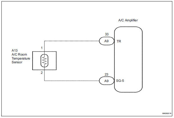
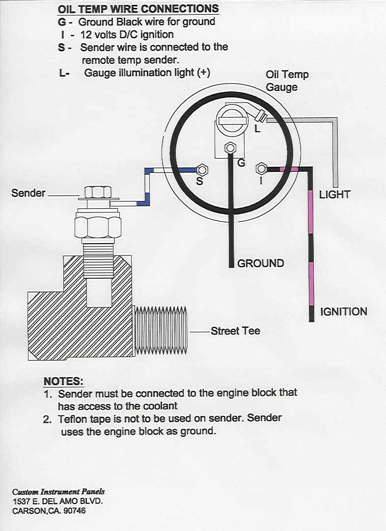
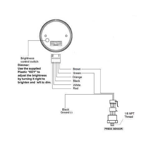
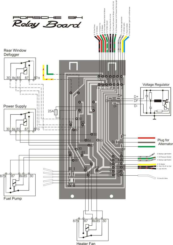
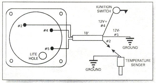
Temperature sensor wiring diagram. Some are connected to the top of the thermostat housing attached to a sensor probe. See how it all ties together in the ecm engine control module. So is there 2 wires both a yellow and black wire in the wiring harness provided for the connector going to the sensor like in the schematic at nevada545 posted above. The linked images are printable but may print across more than 1 page in order to be legible. Workaround that avoids the replacement of the ac evaporator sensor from all ford fusions up to 2012. The supply to the sensor is provided by a sine wave generator based on a1 and a2 see diagram.
4 and 5 testing completed wiring when properly connected the sensor will display outdoor temperature when the up and down buttons on the. The wire length can be reach up to 100m. Front and rear fan. Refer to your owners manual for the location of your existing temperature sensor wire. Air mix door control. Electronic automatic temperature control wiring diagram of 2001 nissan quest v41 2001 nissan quest v41 series electronic automatic temperature control eatc system feature.
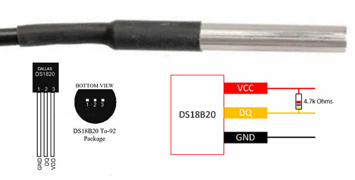
The ds18b20 has four main data connection. The lm45 sensor is powered by an alternating voltage while its output is a direct voltage. The wiring for this method will be the same as for mounting the sensor under the unit. The digital ds18b20 sensor provide fairly good accuracy and range of connection. Presented using advanced software cg animation technology to help. The dht11 measures temperature with a surface mounted ntc temperature sensor thermistor built into the unit.
To learn more about how thermistors work and how to use them on the arduino check out our arduino thermistor temperature sensor tutorial. In this illustration we will going to wire the ds18b20 single wire temperature sensor. A problem that ford should take care in guarantee considering the poor quality of the sensor used and because it is a recurring problem on several. Two wire temperature sensor circuit diagram. Other wires can be found in the side of the engine block where the sensor probe screws into a mounting flange. 64bit layered rom 2.
Route sensor wires into control box wiring area and connect as instructed for procedure 2 above. Ill add ive had some difficulty in the past with coolant temp sensors getting the version with the correct number of leads to match my corollas corresponding connector. Most models also have black white only. With the plastic housing removed you can see the electrodes applied to the substrate.
Gallery of Temperature Sensor Wiring Diagram