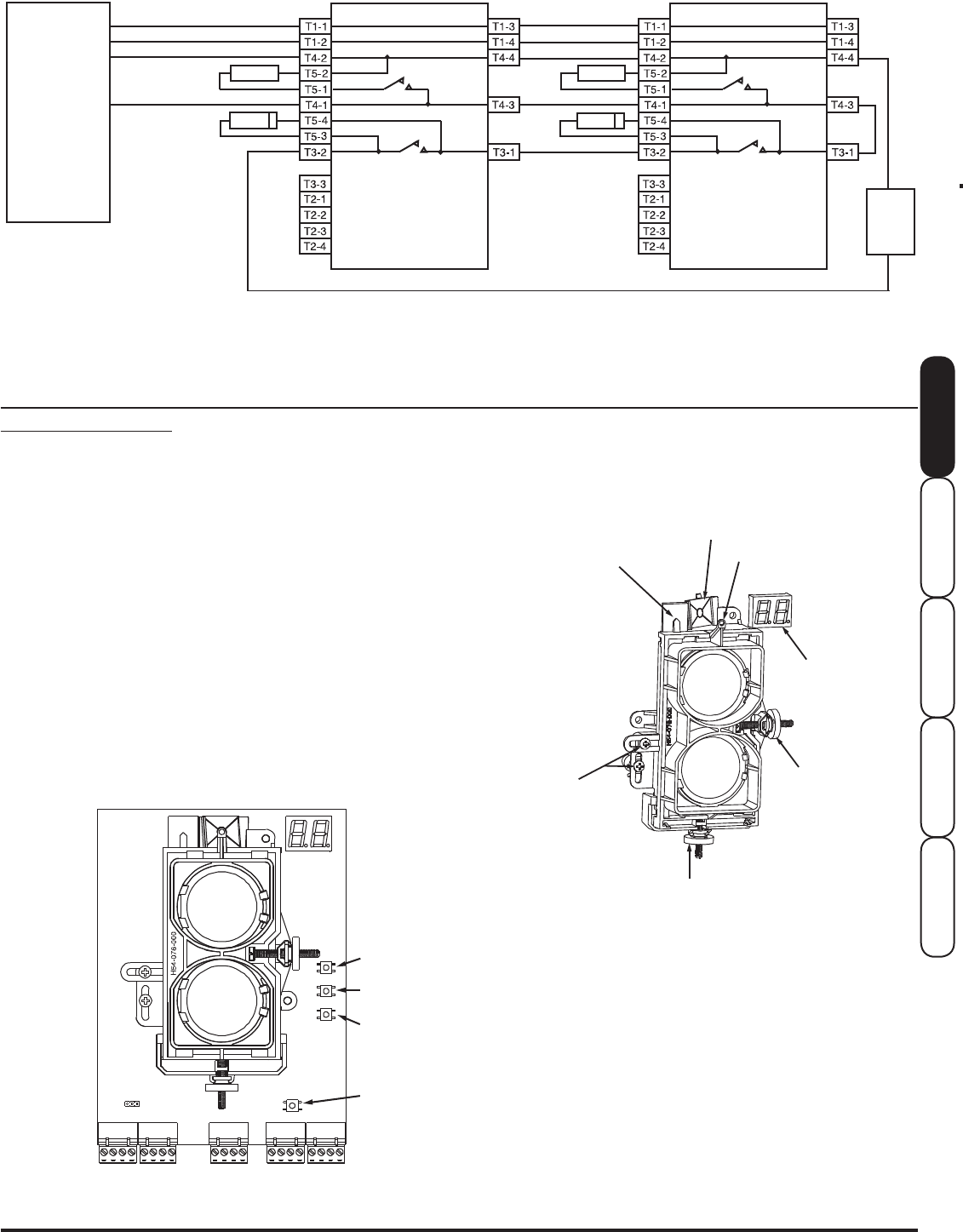
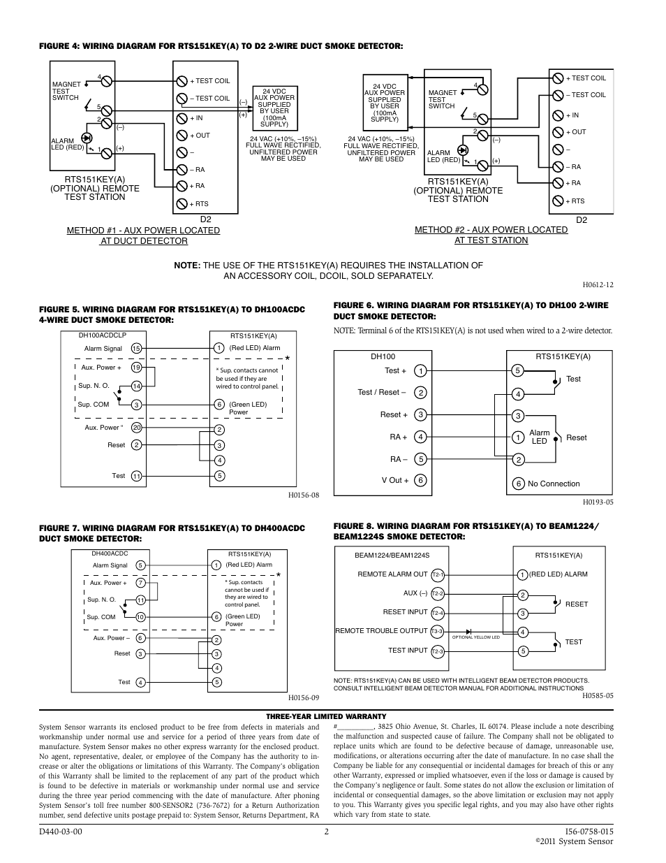
The rts151key mounts to a single gang box 2 12 minimum depth or directly to the wall or ceiling. Wiring diagram for rts151keya to dh100acdc 4 wire duct smoke detector.
System Sensor D4120 Wiring Diagram
System sensor rts151key wiring diagram. Dh100acdclp rts151keya red led alarm. In canadian applications the rts151key a is intended to be located in the same room as the smoke detector and within 60 feet 1829m of the unit. Resetting only certain system sensor models of detectors. Refer to detector installation instructions for additional information. Wiring diagram for rts151keya to dh100 2 wire figure 5. Read system sensors applications guide for duct smoke detectors hvag53 which provides information on detector spacing placement zoning wiring and special applications.
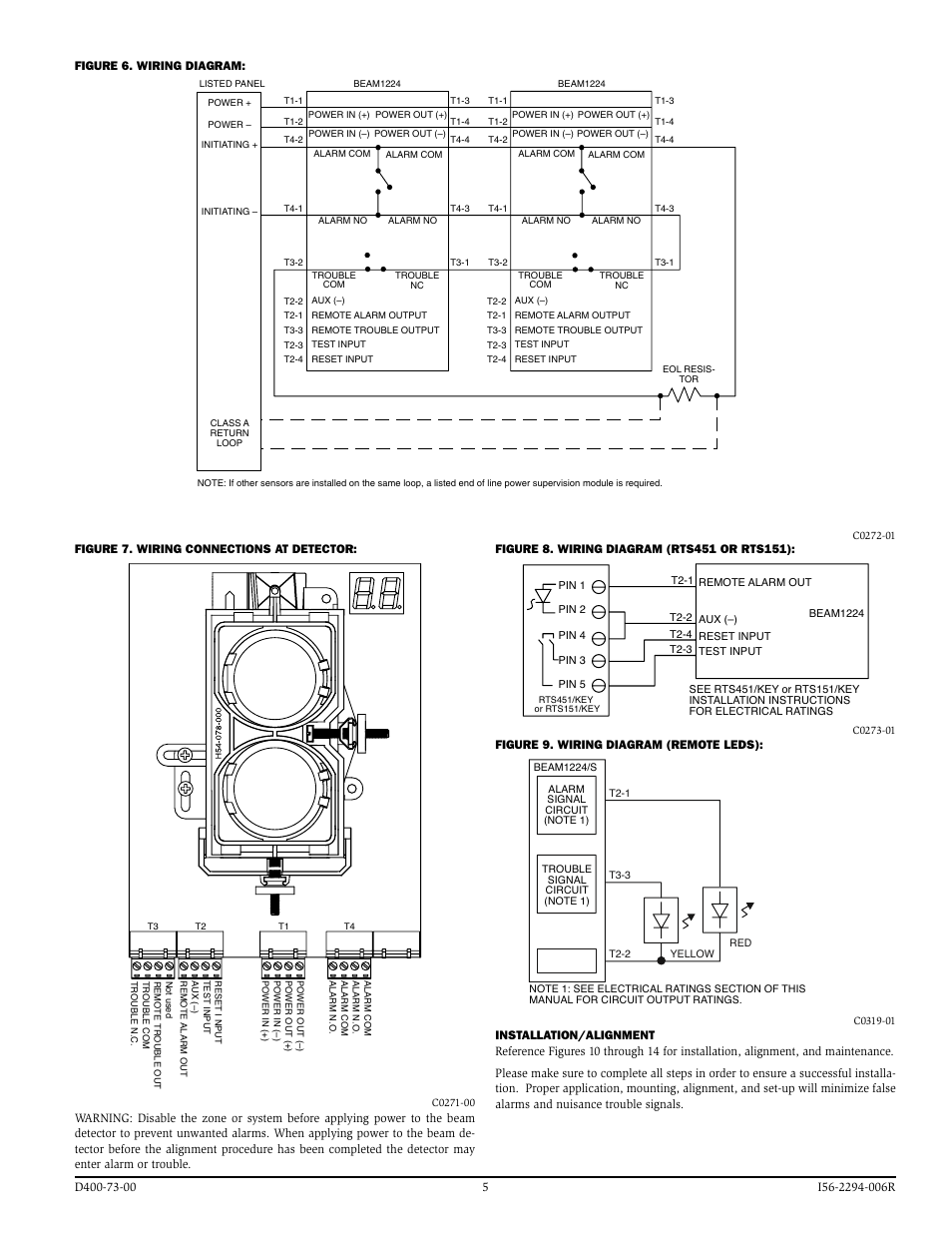
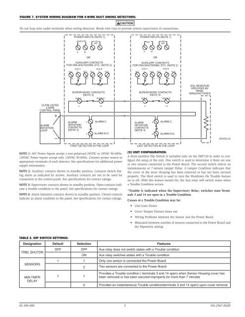
Power reset test red led alarm. Wiring diagram for rts451 to dh100acdc 4 wire duct smoke detector figure 3. Wiring diagram for rts451 to dh100 2 wire duct smoke detector 15 20 2 11 2 alarm signal 1 aux. 4 wire duct smoke detector. Wiring diagram for rts151 to dh400acdc duct. System sensor is a global manufacturer of fire and life safety devices in smoke detection carbon monoxide detection and notification technology.
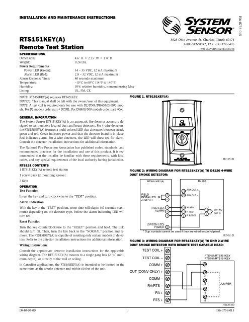
Terminal 6 of the rts151keya is not used when wired to a 2 wire detector. 15 19 14 3 20 2 11 2 6 alarm signal 1 aux. Wiring diagram for rts151key a to d4120a 4 wire duct smoke detector figure 3. Power reset test red led alarm dh100acdc rts151 5 4 3 reset field installed jumper 1 2 3 4 5 6 3 4 test 5 test reset reset test ra 1 reset ra 2 v out dh100 rts151 6 alarm led no connection h0198 04 h0612 11 h0197 01 figure 7. For 4 wire detectors. Nfpa standards 72 and 90a should also be referenced for detailed information.
Wiring diagram for rts151keya to dh100acdc duct smoke detector. Osi r ssosi ra ss single endedreflected typeprojectedimaging beamsmokedetector conventional installationguide october2018 documentnoe56 6572 0013377701. Wiring diagram for rts151key a to d2a 2 wire duct smoke. For 4 wire detectors the rts451key features a multi colored led that alternates between steady green and red. Green indicates power and that the detector board is in place. Wiring diagram for rts151keya to dh100 2 wire duct smoke detector.
Power reset test red. 15 20 2 11 2 alarm signal 1 aux. Terminal 6 of the rts151keya is not used when wired to a 2 wire detector. Rts151key products system sensor system sensor. Wiring diagram for rts151 to dh100 2 wire duct smoke detector. Off reset test h0195 01 h0582 13 figure 1.
The system sensor rts451keya is an automatic fire detector accessory designed to test remotely located duct and beam detectors. The system sensor rts151key is an automatic fire detector accessory de signed to test remotely located duct and beam detectors.
Gallery of System Sensor Rts151key Wiring Diagram