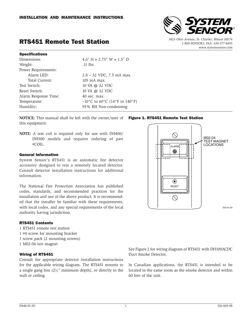
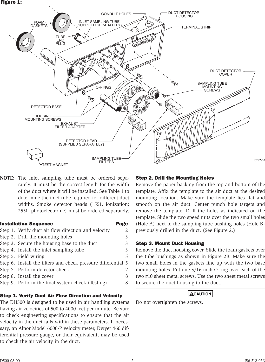
Refer to detector installation instructions for additional information. Duct smoke detector the system sensor ductsd series duct smoke detectors with a cover integrated smoke test port and fl exible confi gurations provides effi cient installation and maintenance.

Smoke Detector Wiring Diagram Electrical Wires Amp Cable Fire
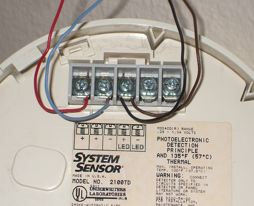
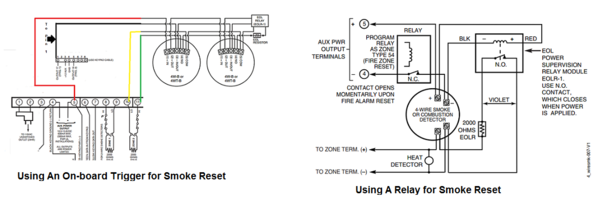
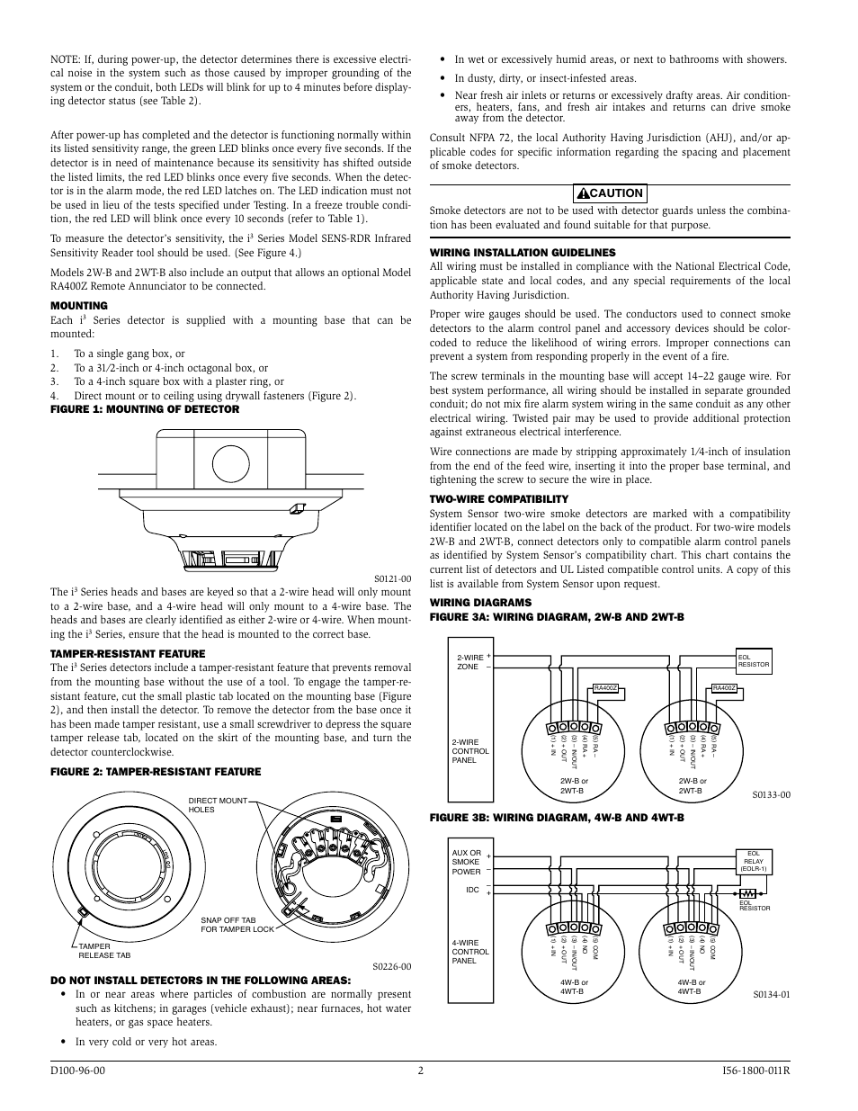
System sensor duct detector wiring diagram. Read system sensors applications guide for duct smoke detectors hvag53 which provides information on detector spacing placement zoning wiring and special applications. Features 4 wire photoelectric integrated low flow technology air velocity rating from 100 ftmin to 4000 ftmin 05 ms to 2032 msec. Model ductsd duct smoke detectors utilize 4 wire photoelectric technology for the detection of smoke. The detector housing shall be ul listed per ul 268a specifically for use in air handling systems. Resetting only certain system sensor models of detectors. Wiring diagram shown is for dh100acdci 4 wire duct smoke detector system equipped without a control panel.
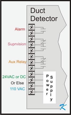
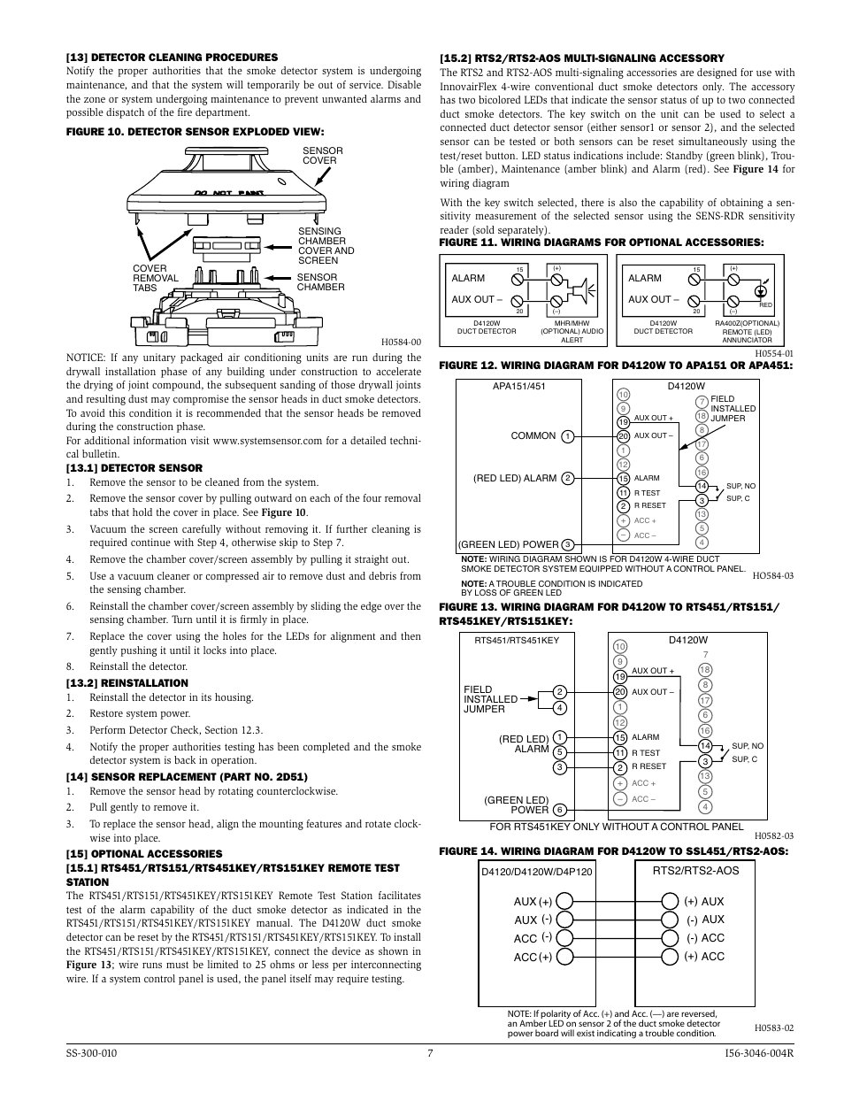
Power reset test red led alarm. 15 19 14 3 20 1 3 alarm signal 2 aux. Smoke detectors designed for use in air duct systems are used to sense the presence of smoke in the duct. Variety of duct smoke detector wiring diagram. A wiring diagram is a simplified traditional pictorial depiction of an electric circuit. Smoke introduced into an air duct system will be distributed throughout the entire building.
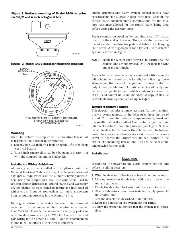
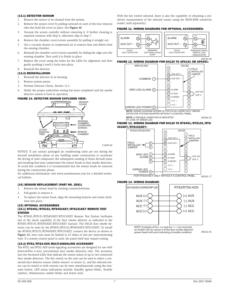
The air duct smoke detector shall be a system sensor innovairflex d4120 photoelectric duct smoke detector. The flexible housing of the duct smoke detector fits multiple footprints from square to rectangular. It shows the elements of the circuit as simplified forms and the power as well as signal links in between the gadgets. Wiring guide system wiring diagram for 4 wire duct smoke detectors wiring diagram for dh100acdci to ssk451 and interconnect feature. Wiring guide system wiring diagram for 4 wire duct smoke detectors wiring diagram for dh100acdclp to ssk451. 24 v ac 10 15 full w ave rectified unfil tered power ma y be used rts151rts151key optional remote test station magnet test switch alarm led red 4 5 2 1 ra rts ra test coil test coil in out.
Alarm red led power green led common. Wiring diagram for rts451 to dh100acdc 4 wire duct smoke detector figure 3. Wiring diagram shown is for dh100acdclp 4 wire duct smoke detector system equipped without a control panel. It shows the components of the circuit as streamlined shapes as well as the power as well as signal links between the gadgets. Nfpa standards 72 and 90a should also be refer enced for detailed information. 15 19 14 3 20 1 3 alarm signal 2 aux.
System wiring diagram for 2 wire duct smoke detectors powered from initiating device circuit. Wiring diagram for rts451 to dh100 2 wire duct smoke detector 15 20 2 11 2 alarm signal 1 aux. Alarm power common. Assortment of system sensor smoke detector wiring diagram. This detection method when combined with an. A wiring diagram is a simplified traditional pictorial depiction of an electric circuit.
Gallery of System Sensor Duct Detector Wiring Diagram