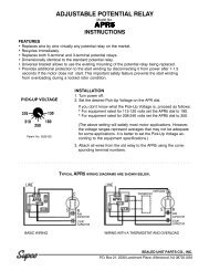
Supco relay wiring diagram wiring diagram is a simplified pleasing pictorial representation of an electrical circuitit shows the components of the circuit as simplified shapes and the aptitude and signal links between the devices. A statement from supcos supplier universal uv solutions.
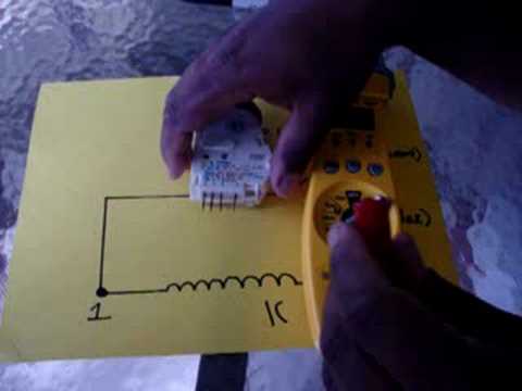
How To Check A Refrigerator S Defrost Timer
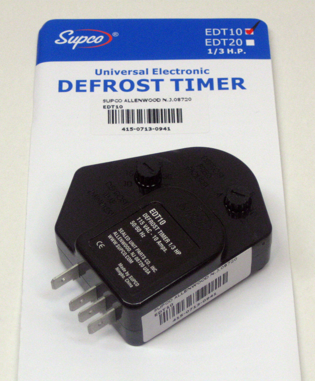
Supco edt11 wiring diagram. Electronic defrost timer 120v 15a. 3 of the original wiring lead 2 to no. 115 vac 34 hp 20 amp defrost timerthe edt series defrost timers utilize adjustable timing and industry standard wiring to replace most domestic and many commercial defrost timersthe new energy efficient edt. Edt11 electronic defrost timer 120v 15a. 1 and lead 4 to no. Edt20 edt20 electronic defrost timer 208 240v 5a.
A wiring diagram usually gives information just about the relative point and covenant of devices and terminals on the devices to support in building or. A wiring diagram is a simplified conventional photographic depiction of an electric circuit. In these applications use the supco no. Variety of supco 3 in 1 wiring diagram. Electronic adjustable defrost timers were de. It reveals the elements of the circuit as simplified shapes as well as the power and signal links between the devices.
Wh4 four wire adapter harness kit if needed. It comes in both 115 and 230 volt units to match your refrigerators compression unit. Wire harness lead 1 to no. Edt11 edt11 electronic defrost timer 120v 15a. The edt series defrost timers utilize adjustable timing and industry standard wiring to replace most domestic and many commercial defrost timers. 4 lead 3 to no.
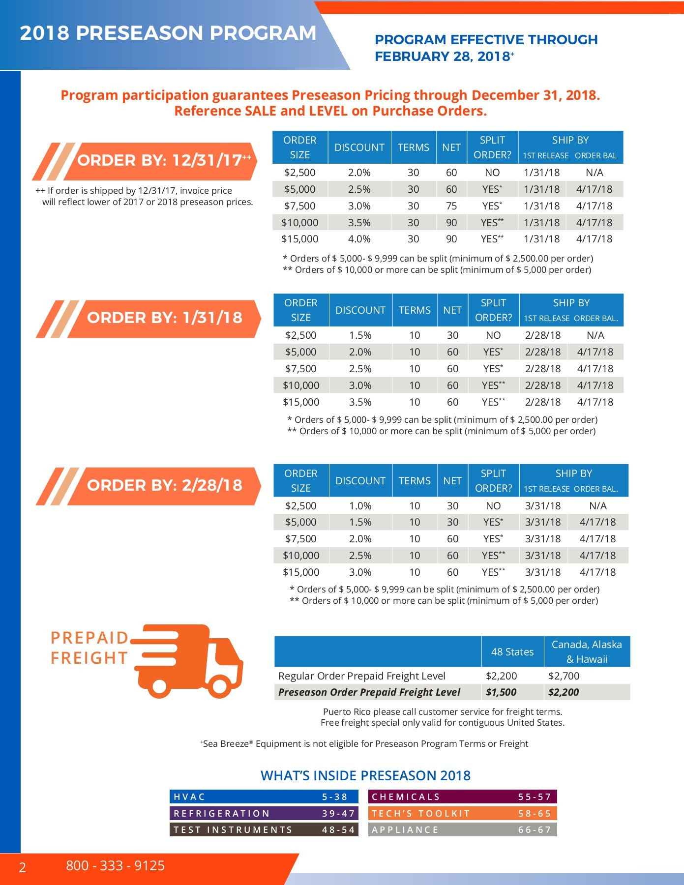
2018 updated appliance catalog. 32f to 135f 0c to 57c. Wire a supco 3 n 1 relay box to your refrigerators compressor. Supco rco 3 n 1 is a relay box that can be wired directly into your refrigerator units compressor.
Gallery of Supco Edt11 Wiring Diagram