Loosen the silver and brass terminal screws on the line side of the outlet. The wires attaching to the gfi outlet connect to the line side.
Gfci Switch Outlet Wiring Diagrams Do It Yourself Help Com
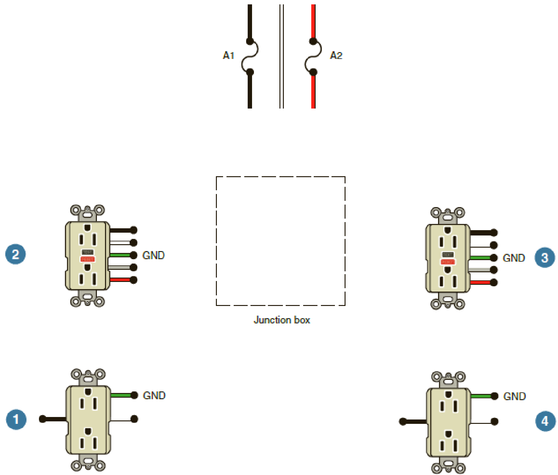
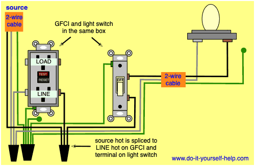
Single gfci wiring diagram. One side of the gfci connected to the ground neutral wire as shown white in the diagram and another side to the high potential hot wire shown as black in the diagram shows as in black color. Wiring diagrams are. If more than 1 black and 1 white conductor are in the electrical box also loosen the load side silver and brass terminal screws. Wiring diagram for gfci and light switch wiring diagram is a simplified up to standard pictorial representation of an electrical circuit. The hot source is spliced to the line terminal on the receptacle and to one terminal on the light switch. Ground fault circuit interrupters gfcis gfci load wiring.
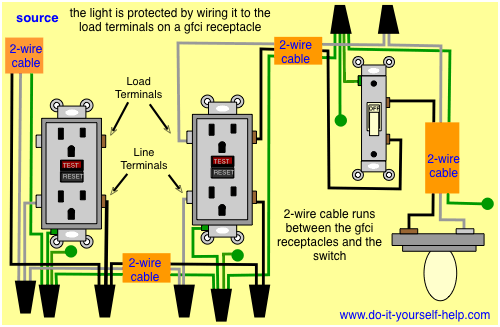
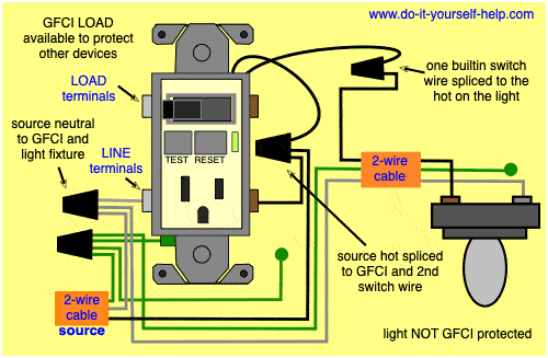
Gfci load wiring diagram. This gfi outlet comes with yellow tape over the load side. The wires attaching to the gfi outlet connect to the line side. This way the switch and light bulb is gfci protected. This example of wiring a single gfci receptacle outlet shows a outlet box with one pair of wires form a 2 wre cable with a ground wire. This gfi outlet comes with yellow tape over the load side.
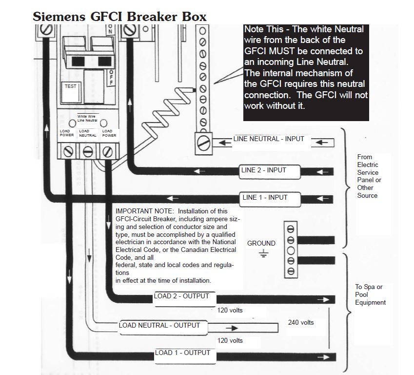
It shows the components of the circuit as simplified shapes and the capacity and signal friends in the midst of the devices. The above diagram shows the gfci wiring to multiple outlet as in white while the pictures are same. The neutral and ground wires are spliced together and run to each device in the circuit. The lower four terminals and ground wire of rcbo has been connected to the spa control box by the following sequence. Single gfci wiring diagram gallery leviton gfci wiring diagram new gfci wiring diagram without ground gfci outlet wiring diagram best great at exactly whats wiring diagram. How to wire gfci combo switch and outlet gfci switchoutlet wiring diagrams.
In the first diagram the single way switch and light bulb is connected to the load terminal of gfci. This diagram illustrates wiring a gfci receptacle and light switch in the same outlet box a common arrangement in a bathroom with limited space. In this example the gfi protection serves this outlet location only. A wiring diagram is a sort of schematic which utilizes abstract photographic symbols to reveal all the interconnections of parts in a system. Refer to the diagram above about wiring gfci receptacles for additional help. Wiring a gfci outlet with a light switch.
Arc fault circuit interrupters afcis. This example of wiring a single gfci receptacle outlet shows a outlet box with one pair of wires form a 2 wre cable with a ground wire. The three phase wiring for gfci or rcd rccb or rcbo wiring diagram shows the three lines l1 l2 and l3 and neutral has been connected as input to the rccb from main board followed by mcb ie.
Gallery of Single Gfci Wiring Diagram

/cdn.vox-cdn.com/uploads/chorus_asset/file/19585969/wiring_problems_xl_banner.jpg)