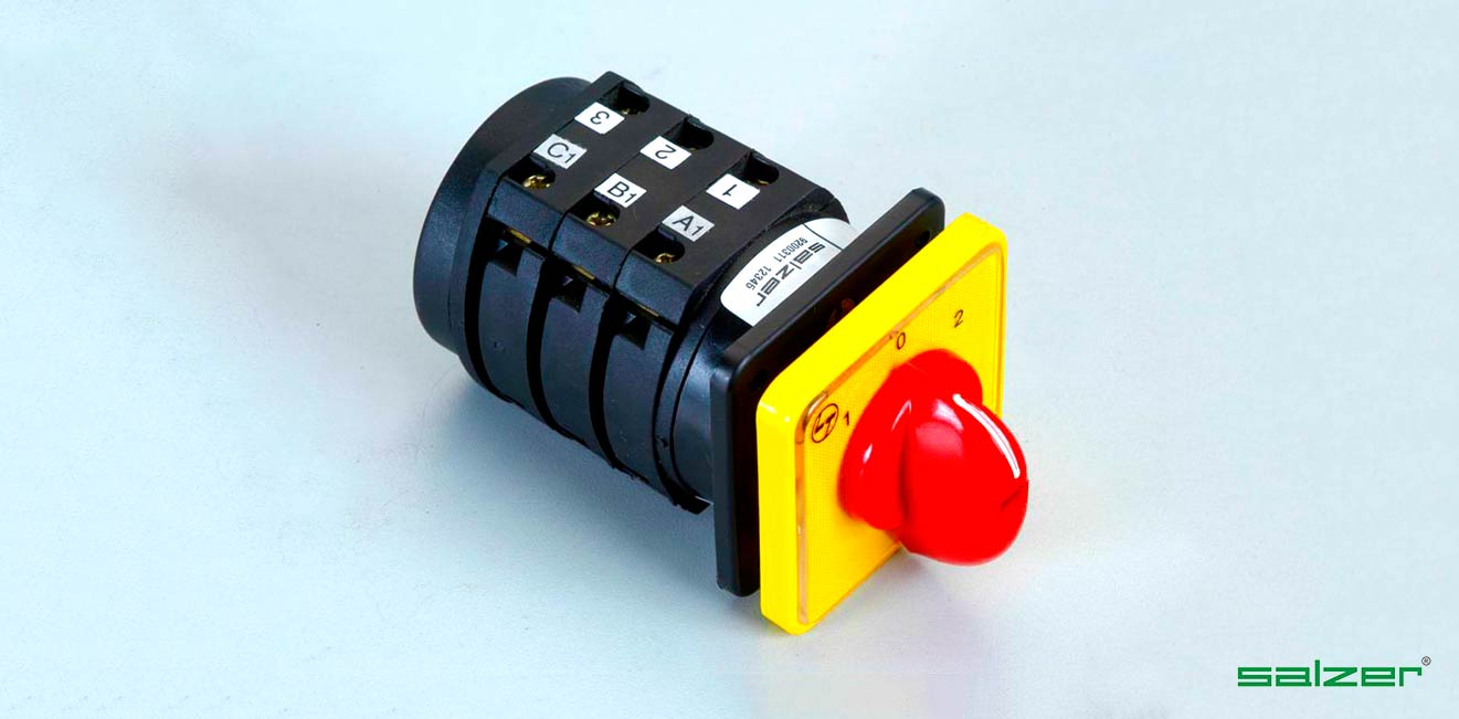
Authorization a section circuit diagram example for salzer is a well known name in the field of. Cam operated rotary switches used to perform make and break operation instrumentation selector switches.
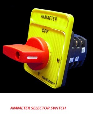
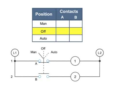
What Is Ammeter Selector Switch
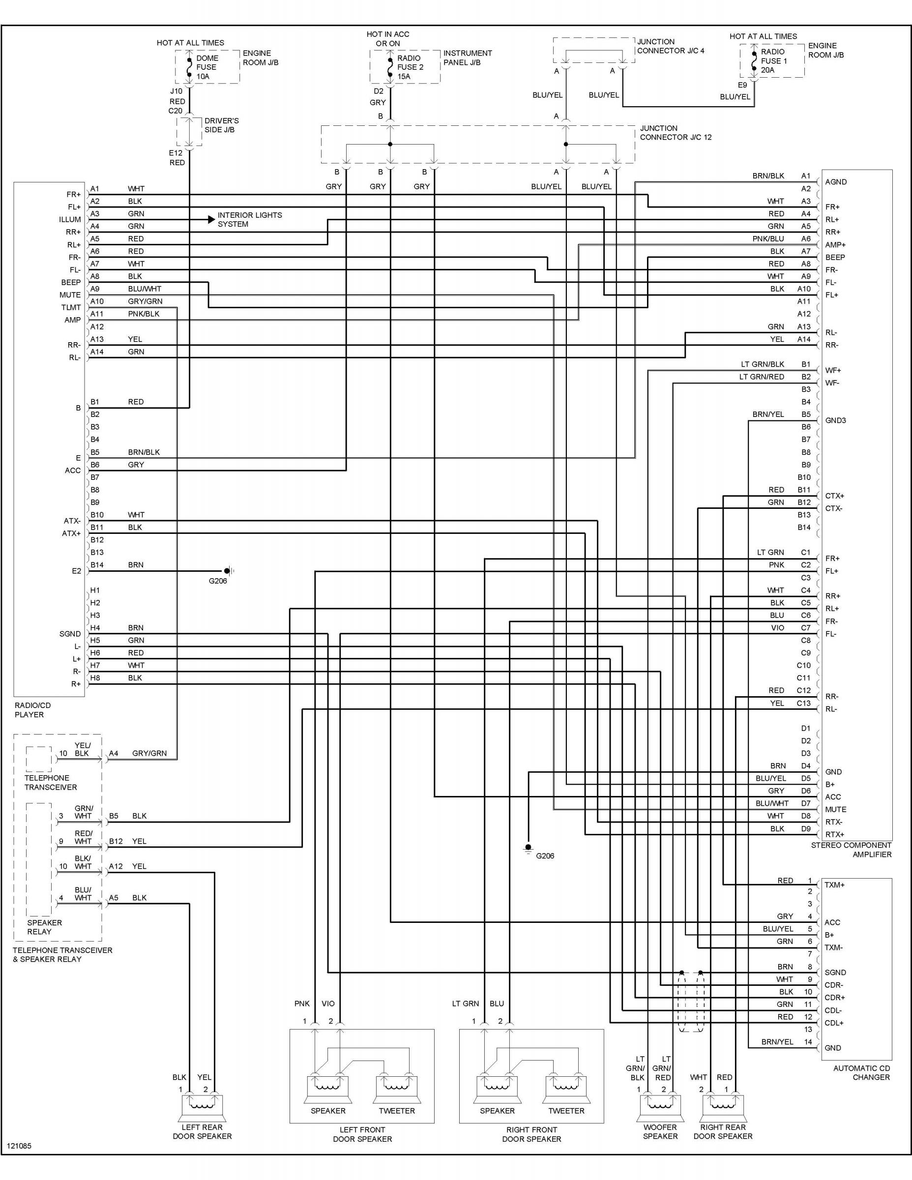
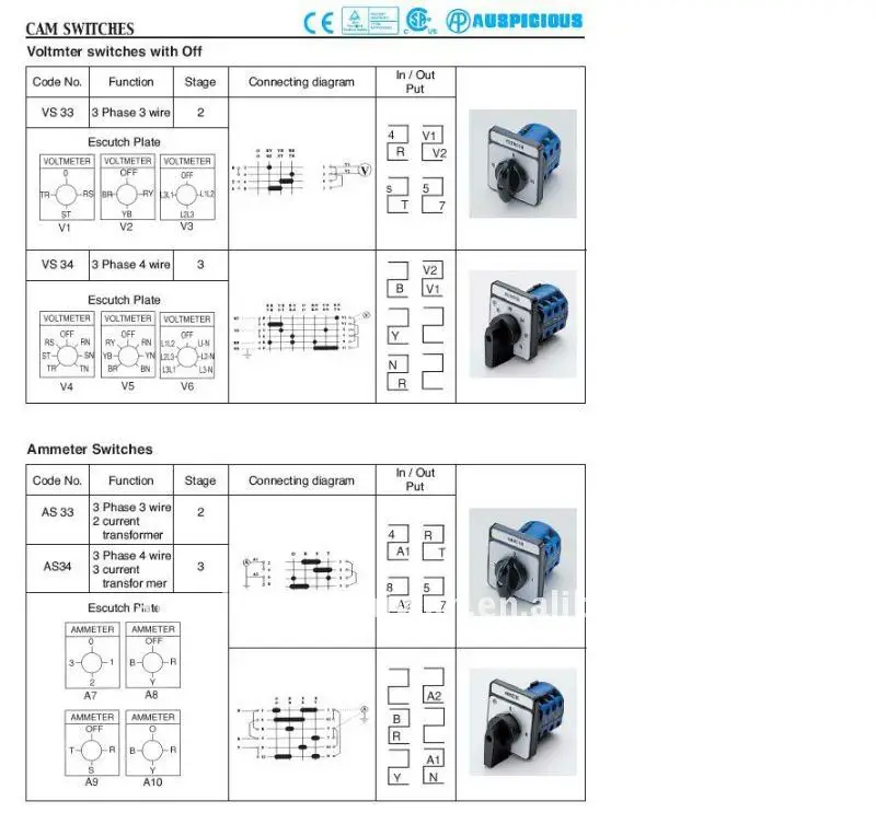
Salzer rotary switch wiring diagram. Technical information rotary cam switches switching diagrams 61331 61485. 20a 2 these switches have 2 to 8 positions and 1 to 12 stages 3 widely used to change position of ammeter and voltmeter to control the direction of mot. Plug black to switch 1 white plug to switch 3 wire nut to switch green green electric cable from motor to switch. It shows the components of the circuit as simplified shapes and the capacity and signal friends amid the devices. Ammeter switches with 0 position start selector switches. Wiring diagram for salzer reversing drum switch for use with 314 h 1 hp and 15 hp east bay motors gfci plug to switch.
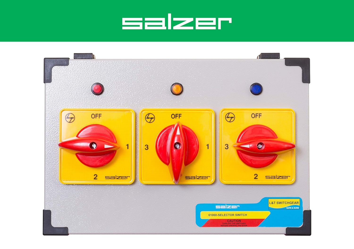
Technical information rotary cam switches switching diagrams 61918 61932. Salzer selector switch 20a. Pole change switches and reversing pole change switches page 363. Rotary rotary switches and switch disconnectors with atex. Technical information rotary cam switches switching diagrams 61625 61917. Red to 4 black to 8 orange to 12 vnhmtce to 2 wire nut to gfci green green.
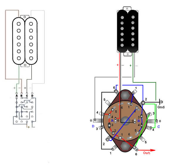
Rotary cam switches from salzer are manually operated independently programmable. Salzer rotary switch wiring diagram wiring diagram is a simplified conventional pictorial representation of an electrical circuit. Switching diagrams and further switching programmes page detailed. Moeller wiring manual 02 4.
Gallery of Salzer Rotary Switch Wiring Diagram