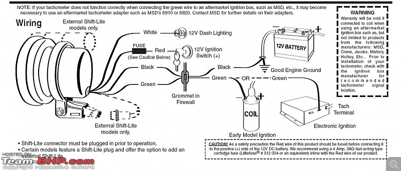
Tachometer with built in shift lights for professional racing follow the instructions in the programming flow diagram to. Cf5135b rpm speedometer wiring manual duration.
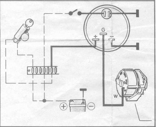
Wiring Diagram For Aftermarket Tachometer
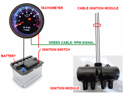
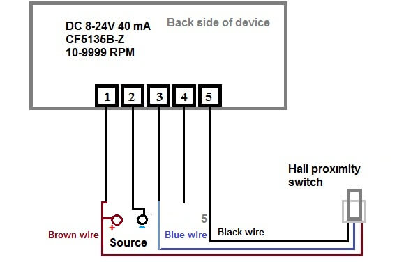
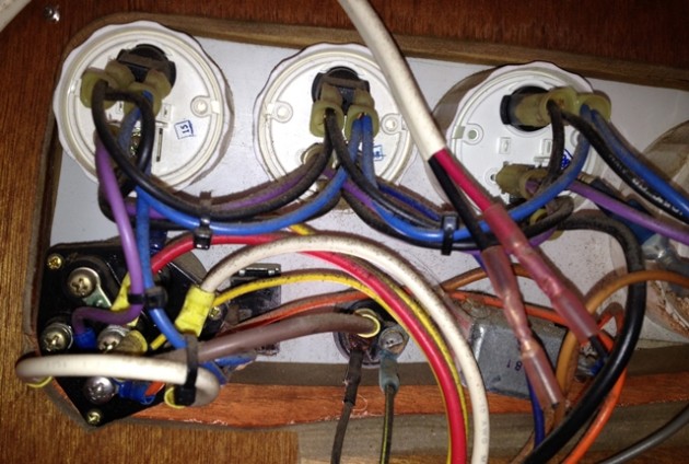
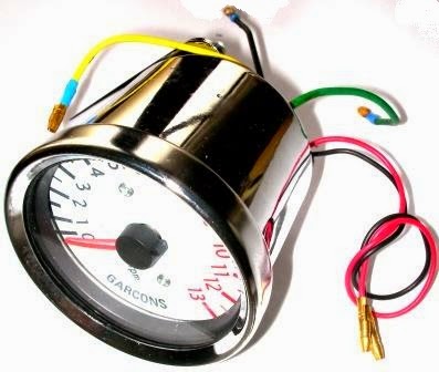
Rpm meter wiring diagram. Cable dca analog cable diagram. Cable dcr rpm cable. 46 48 50 52 54 x rpm. Be sure to mark or remember the wire for when you come back later. The positive power pole is connected to the brown wire for the magnetic sensor negative power pole speed sensor blue wire from the sensor fourth position nothing connect. On vehicle tachometer is measuring engine speed.
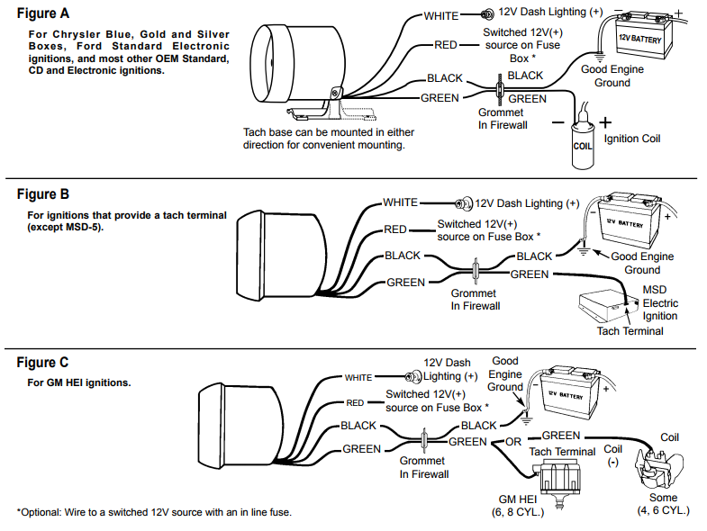
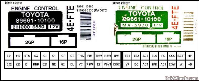
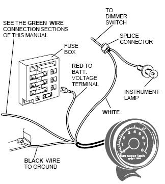
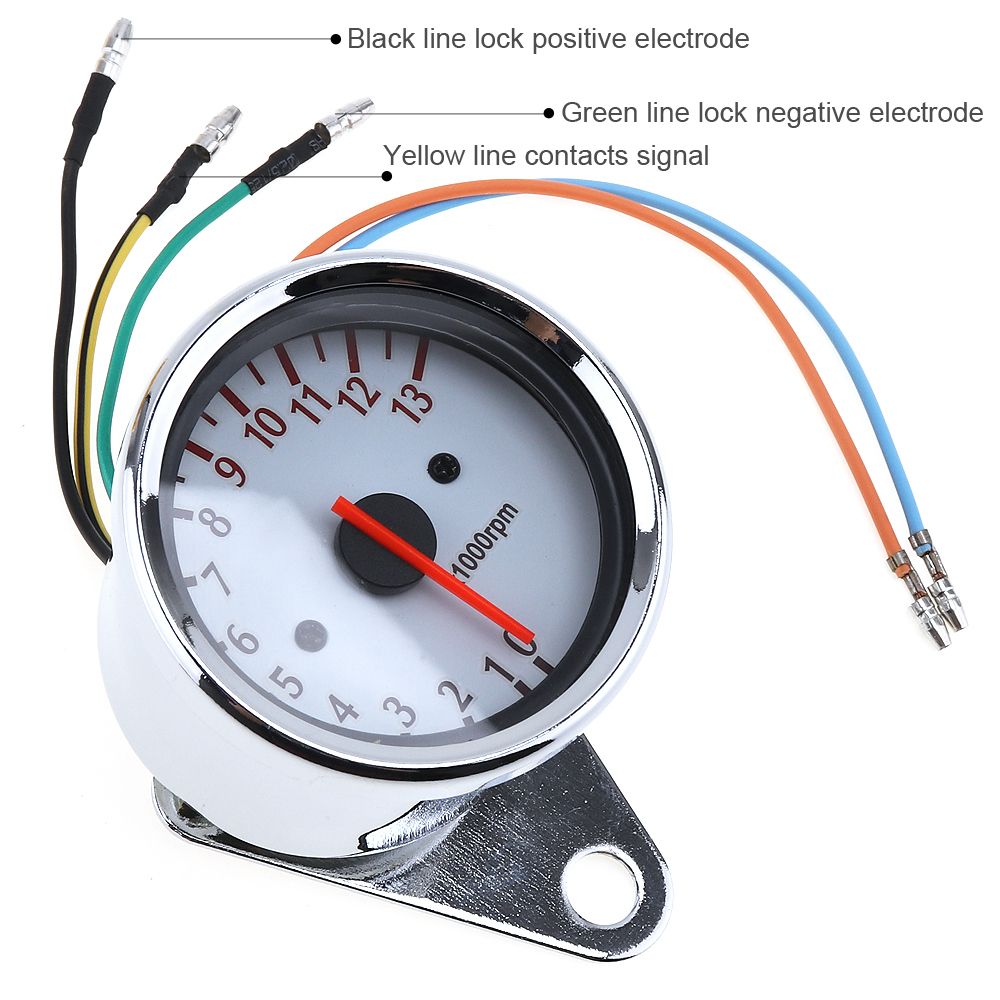
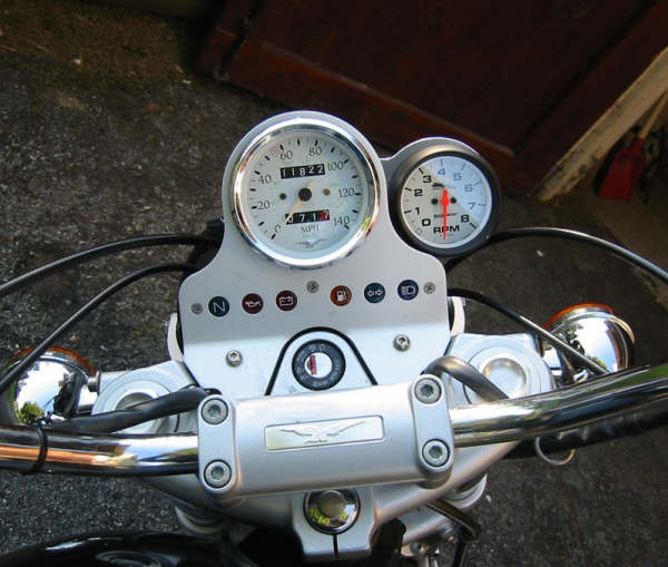
The rpm device must be rotated by the display down then the correct wires according to the diagram on the back. Wiring diagram for aftermarket tachometer a tachometer is gauge to measure mechanical speed in units of rpm revolutions per minute or rotations per minute. Here is a description of electrical wires on connector. To be sure it was the right one i had someone watch the meter as i revved the engine. For operation on 4 or 6 cylinder engines a switch adjustment must be made. Form 2s need a meter for a 120 volt circuit.
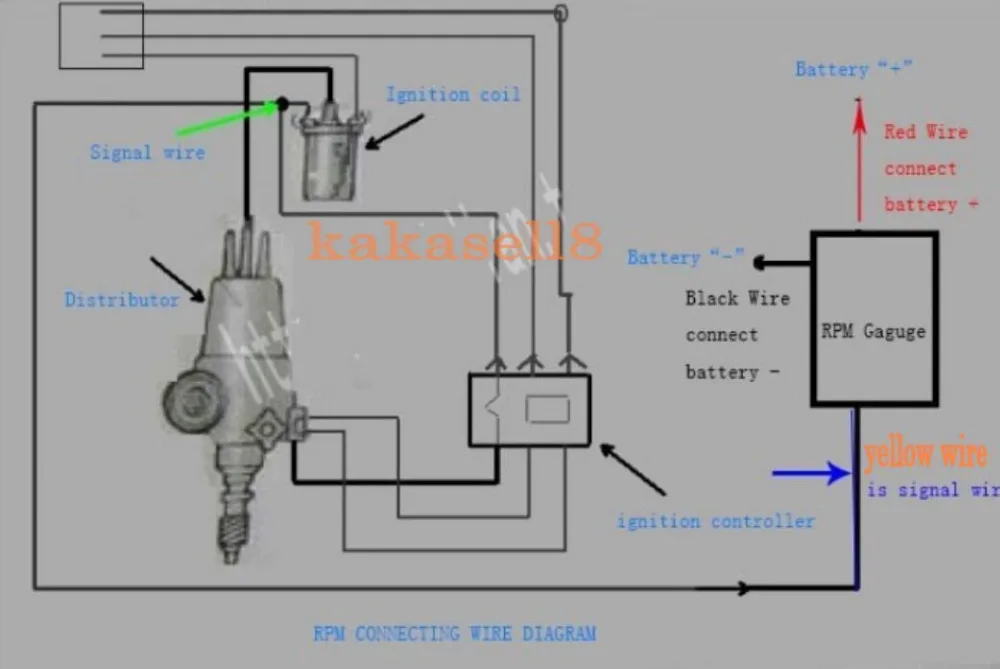
I connected the black wire to the side of the battery and the red to the. Model 2300 2301 2302 2303 2304 2309. Download your wiring diagrams here. This diagram shows how to wire it for 120v. Single phase form 2s for 240v circuit. Search through our list of wiring diagrams to find the right one for your job.
For use on 4 6 or 8 cylinder engines with standard ignitions this product not valid for race contingency money. Cable dcf flowmeter cable. Here is how to wire the chinese digital tachometer. 5 spek pro professional racing gauge. Wiring installation instructions for. Hall effect sensor switch wiring diagram duration.
This tachometer is factory calibrated for 8 cylinder engines. Cable dcrc custom rmp cable. Order our 240 volt meter. Cable dcp power and remote start cable. A photographic diagram would show more detail of the physical appearance whereas a wiring diagram makes use of an extra symbolic notation to emphasize interconnections over physical look. A wiring diagram is commonly made use of to fix problems as well as to earn sure that all the connections have been made which every little thing exists.
56 58 60 62 64 x rpm. Next i clipped the meter wire onto the white wire from the distributor. 36 38 40 42 44 x rpm. Single phase form 2s for 120v circuit. Ive tried this permutation procedure and found it works to my aftermarket tacho meter although my wiring has different color coded. Click here to view and print the full size diagram.
Dual function cable srpm and digital. Hi in this video i describe cf5135b rpm tachometer speedomer how to properly wiring more gut info see on my page.
Gallery of Rpm Meter Wiring Diagram