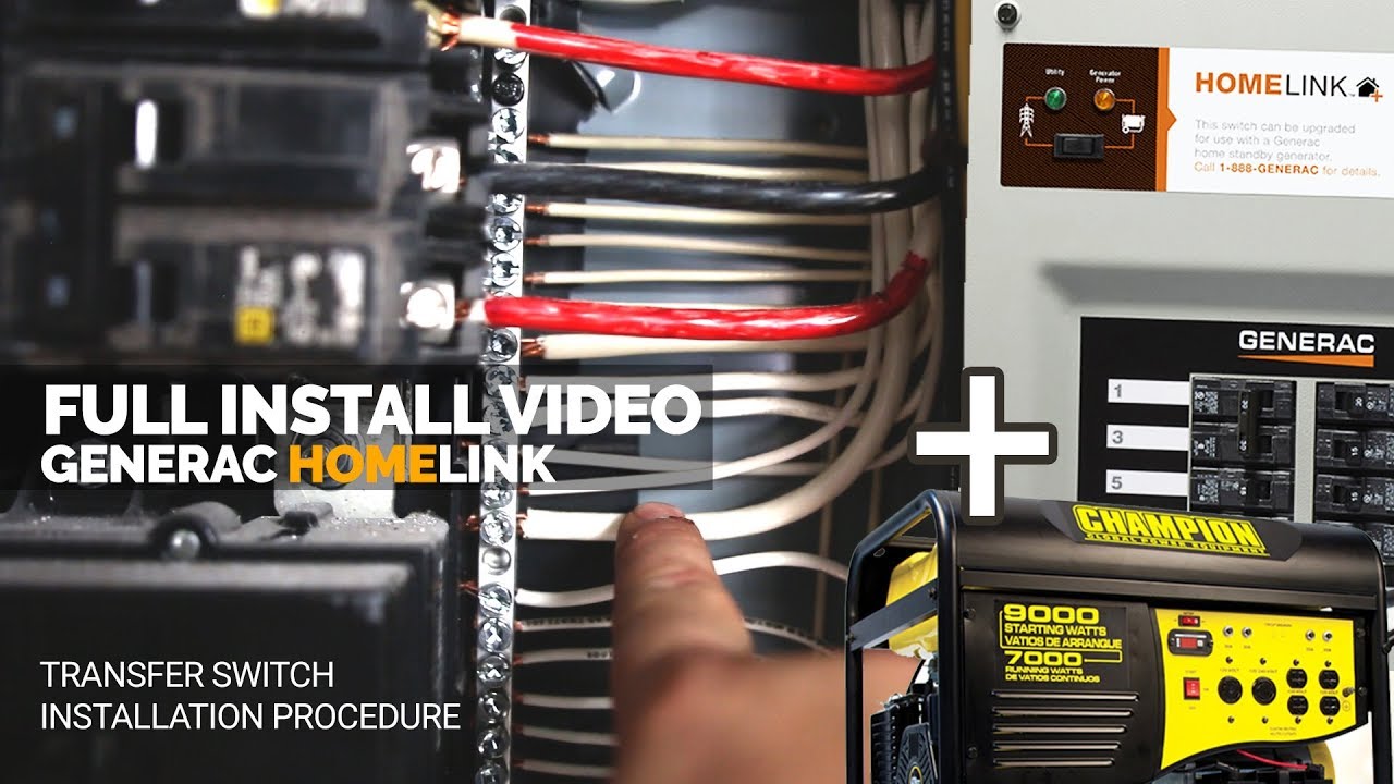
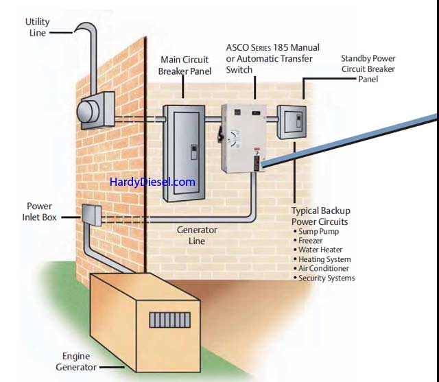
When utility power is functioning the wires from the circuit breaker in the main electrical distribution panel are connected to the generator sub panel. A wiring diagram generally gives details concerning the family member placement and setup of gadgets and terminals on the tools to aid in structure or servicing the tool.

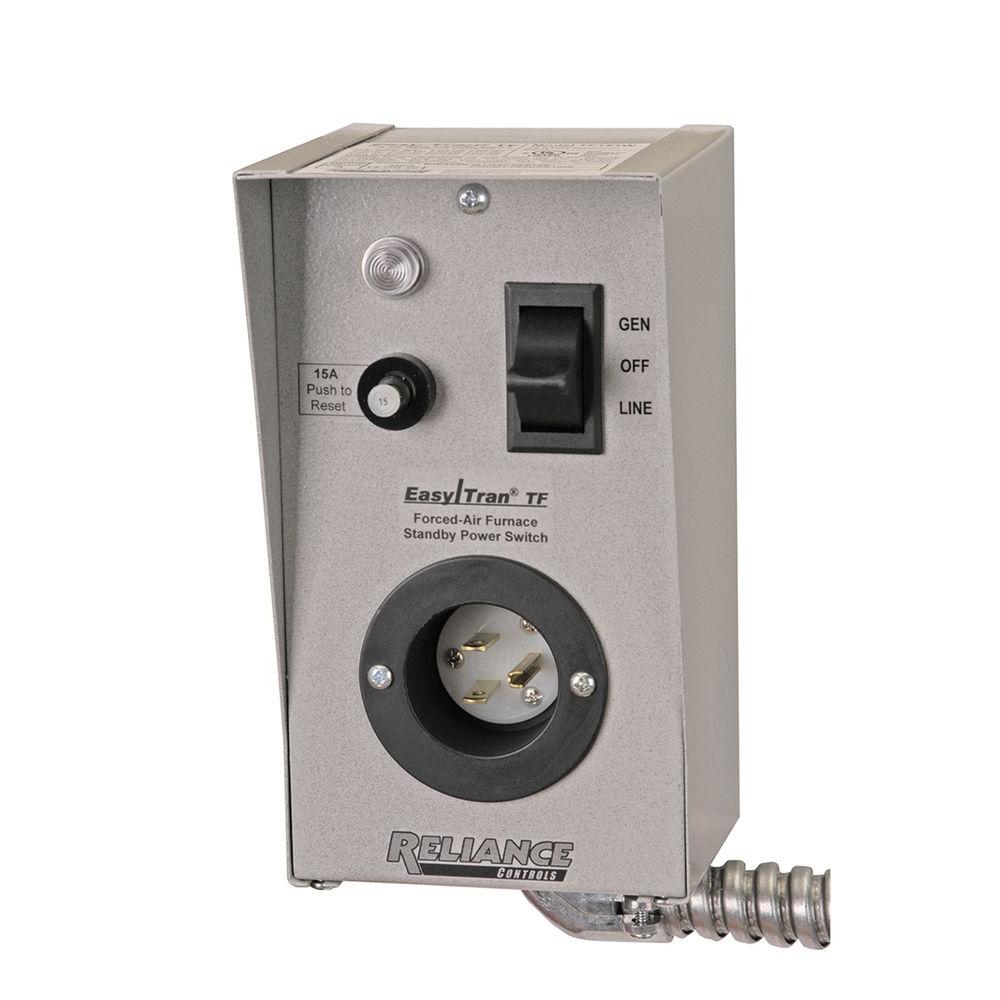
12 5 Kw Home Standby Generator With 100 Amp Outdoor Switch
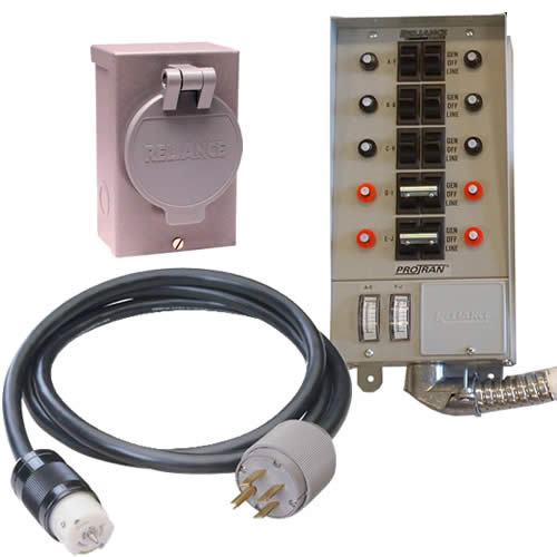
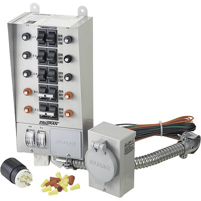
Reliance transfer switch wiring diagram. A wiring diagram normally offers details concerning the relative placement and also setup of gadgets and also terminals on the tools to help in structure or servicing the device. They should join the circuit breaker through a knockout found at the bottom of the box. Panellink x series the xrc series has 10 branch circuit spaces and will allow up to 18 circuits with the use of tandem breakers. The wires should be drawn through 1 of 3 knockouts located on the underside of the switch. Tuck the wires neatly out of the way at the edges of the box. Panellink manual transfer panels and generator ready load centers are available in single or three phase.
A wiring diagram is a streamlined traditional pictorial depiction of an electrical circuit. Variety of reliance transfer switch wiring diagram. If a selected circuit is part of a multi wire branch. The residential wattage requirement chart on the inside front cover of this manual may be used as a guide but actual appliance wattages may vary. Wellborn collection of reliance generator transfer switch wiring diagram. Transfer switch accessories designed to compliment your reliance product.
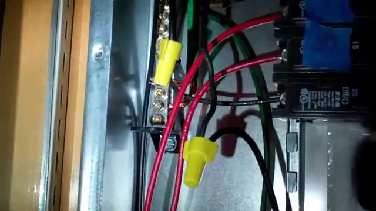
A wiring diagram is a streamlined traditional pictorial representation of an electric circuit. Locate the black wire from the same transfer switch circuit and twist it together with the old feed wire using a yellow wire connector. A wiring diagram is a simplified conventional pictorial depiction of an electrical circuit. Collection of reliance generator transfer switch wiring diagram. Panellink x series. It reveals the parts of the circuit as simplified forms as well as the power as well as signal links between the devices.
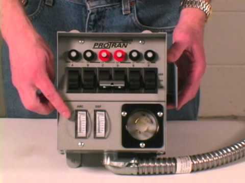
July 8 2019 by larry a. Proceed to the next circuit and repeat the process. Installing transfer switch step 10. Wiring the reliance transfer switch to the load center determine which circuits will be used during an emergency. Figure 5 wiring diagram of a manual transfer switch in the on position. It reveals the elements of the circuit as streamlined shapes and the power and also signal connections in between the gadgets.
It reveals the parts of the circuit as simplified forms and also the power as well as signal links in between the gadgets. Assortment of reliance generator transfer switch wiring diagram. If utility power fails the switch connects the generators power to the circuits in the generator sub panel. It shows the parts of the circuit as streamlined forms and also the power and signal connections in between the tools. A wiring diagram is a streamlined conventional photographic representation of an electrical circuit. Use the transfer switchs wiring harness to connect the unit to the circuit breaker.
Gallery of Reliance Transfer Switch Wiring Diagram