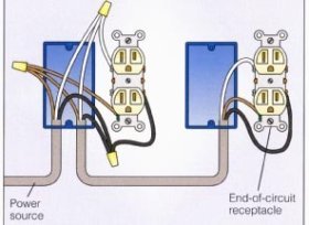
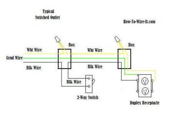
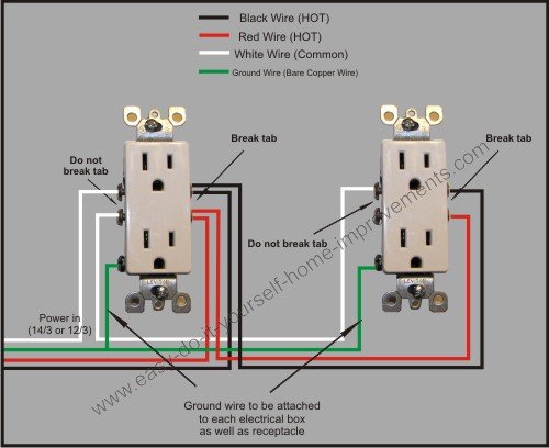
Also shown is the half of the receptacle that is live at all times and the tab that must be cut in order to split the receptacles. In the diagram below a 2 wire nm cable supplies line voltage from the electrical panel to the first receptacle outlet box.
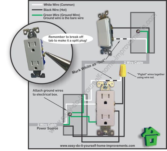
Split Plug Wiring Diagram
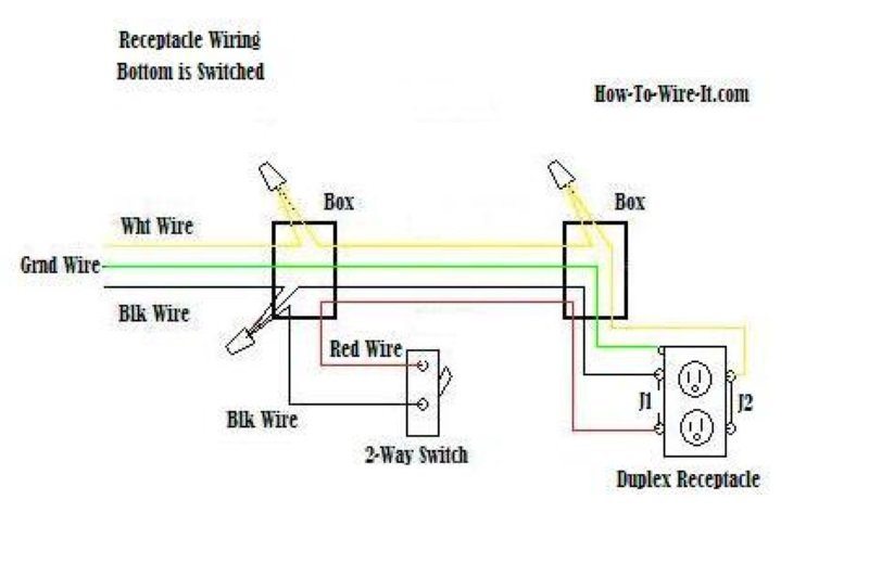
Receptacle wiring diagram. Depicted here is the wiring diagram for controlling the half of two duplex electrical receptacles by a wall switch without a neutral conductor. Multiple outlet in serie wiring diagram. My light switch wiring diagrams may be helpful to you. Diagrams shown on this page are simplified for clarity. To wire multiple outlets follow the circuit diagrams posted in this article. The toggle switch in the combo switch outlet controls the first light bulb while the single way.
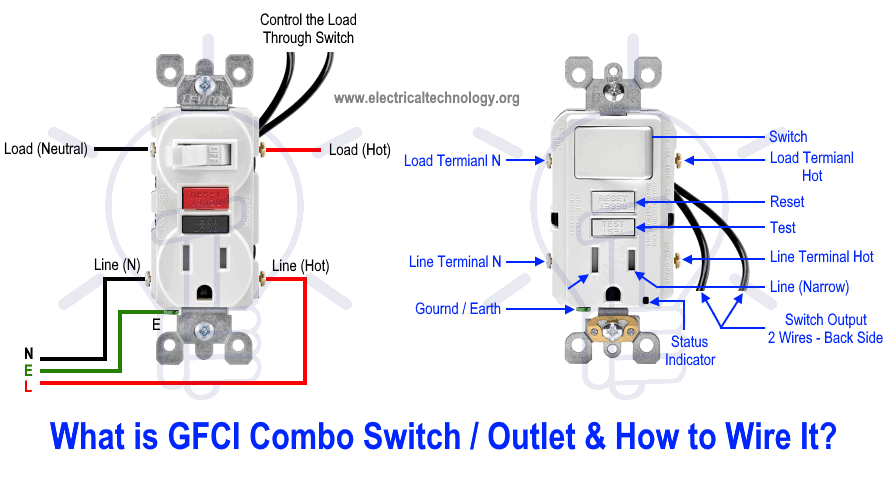
One side of the gfci connected to the ground neutral wire as shown white in the diagram and another side to the high potential hot wire shown as black in the diagram shows as in black color. Two wire cable is run between the gfcis and the hot and neutral wires from the source are spliced to the line terminals at each device. This is a polarized device. This is a standard 15 amp 120 volt wall receptacle outlet wiring diagram. The source is at the outlet and a switch loop is added to a new switch. Wiring a receptacle also referred to as an outlet is another of those fundamental wiring skills that every diyer should feel comfortable undertaking.
In this gfci outlet wiring and installation diagram the combo switch outlet spst single way switch and ordinary outlet is connected to the load side of gfci. Variety of leviton gfci receptacle wiring diagram. Wiring diagram for multiple gfcis. The long slot on the left is the neutral contact and the short slot is the hot contact. Any break or malfunction in one outlet will cause all the other outlets to fail. It means all the connected loads to the load terminals of gfci are protected.
See actual switch box wiring diagram. The black wire from the switch connects to the hot on the receptacle. This wiring diagram illustrates adding wiring for a light switch to control an existing wall outlet. The hot source wire is removed from the receptacle and spliced to the red wire running to the switch. This repeats until the end of the chain. The black wire line and white neutral connect to the receptacle terminals and another 2 wire nm that travels to the next receptacle.
A wiring diagram is a streamlined traditional photographic depiction of an electric circuit. The above diagram shows the gfci wiring to multiple outlet as in white while the pictures are same. Dont use this receptacle when no ground wire is available. For wiring in series the terminal screws are the means for passing voltage from one receptacle to another. It reveals the parts of the circuit as simplified forms as well as the power and signal links in between the tools. In this diagram multiple ground fault circuit interrupter receptacles are wired together using pigtails to connect the source.
A grounded contact at the bottom center is crescent shaped. The 15a 125v receptacle is the most widely used device in your home. Electrical outlet boxes can have numerous nm cables going in and out. This article and detailed wiring diagram explains the steps to wiring the common household receptacleoutlet.
Gallery of Receptacle Wiring Diagram