Keep these instructions with the brake control for future reference. Boost button tow vehicle.

Ha 6196 Wiring Diagram For A Tekonsha Trailer Brake
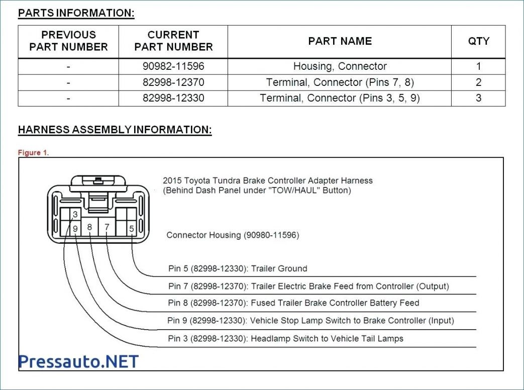
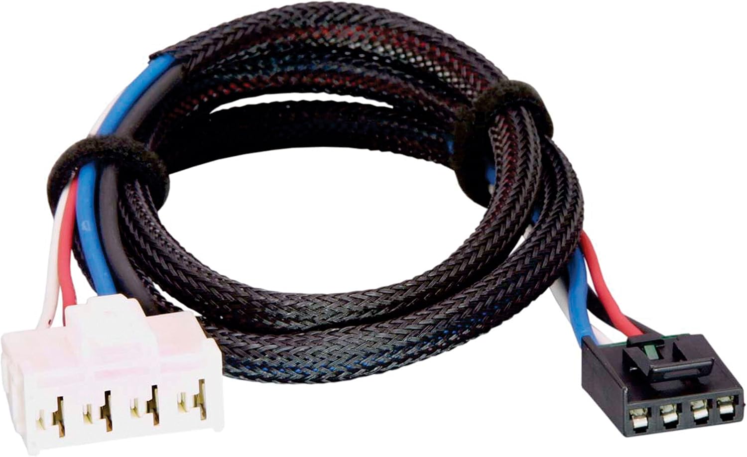
Prodigy brake controller wiring diagram. 7 way cable to b. If not the structure wont function as it should be. Tekonsha trailer brake controller wiring diagram tekonsha electric trailer brake controller wiring diagram tekonsha p3 electric brake controller wiring diagram tekonsha p3 prodigy electric trailer brake controller wiring diagram folks comprehend that trailer is a vehicle comprised of very complicated mechanics. Warning reversing black and white wires or improper wiring will damage or destroy brake control. The brake control for future reference. Connector for wiring harness e.
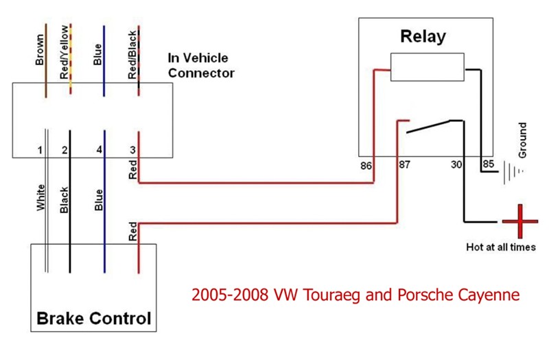
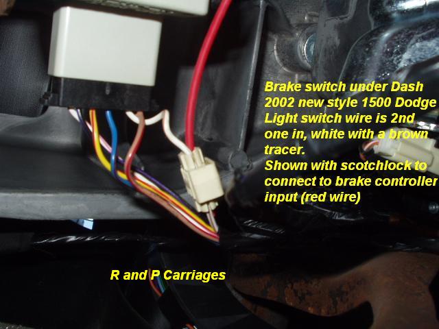
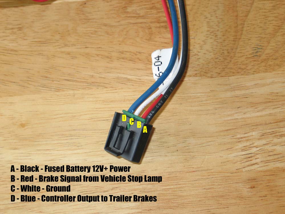
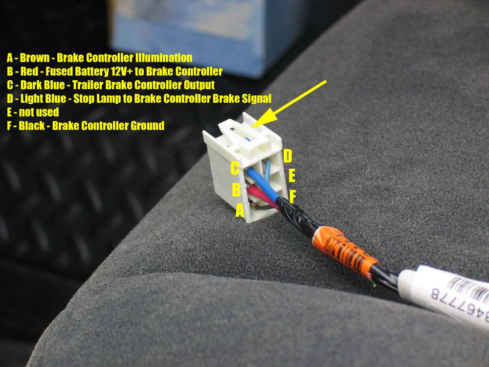
Warning be sure to solidly. Insert prodigy brake control. Red wire carries the brake light input signal and connects to the cold side of the brake light switch the side that carries a signal only when you press the pedal. Do not mount or activate rf generating items cell phones two way radios near. Read and follow all instructions carefully before installing or operating the prodigy rf. Trailer brake controllers like the prodigy p2 90885 use a 4 wire hook up.
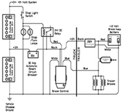
This car is designed not only to travel one location to another but also to. Mounting hole 1 per side important facts to remember 1. Components of prodigy rf a. For 2 4 6 and 8 brake applications components of the brake control a. It shows the elements of the circuit as simplified forms as well as the power and also signal connections between the devices. To install with a positive ground system use tekonsha pn 3191 2.
The brake control must be installed with a 12 volt negative ground system. Collection of prodigy brake controller wiring diagram. Black wire carries 12v power and connects to the vehicle battery post through a 20 or 30 amp circuit breaker like pk54220pl or pk54530. Prodigy brake controller wiring diagram prodigy 3 brake controller wiring diagram prodigy brake controller wiring diagram prodigy brake controller wiring schematic every electric structure is made up of various different components. A wiring diagram is a simplified traditional photographic depiction of an electrical circuit. Prodigy brake controller wiring diagram.
Each component should be set and connected with different parts in particular manner. Important facts to remember 1. Prodigy rf electronic brake control for 2 4 and 6 brake applications read this first. The wire functions and connections are as follows.
Gallery of Prodigy Brake Controller Wiring Diagram