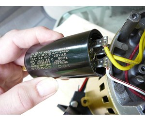
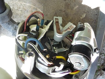
This video shows a diy by an amateur diagnosis of a pool pump problem and the replacement of a failing capacitor on the pump motor. Continuous rated run capacitor provides high running e f ficiency and better starting perf o r mance in low voltage s i t u a t i o n s.

Gv 6707 Pump Start Box Wiring Diagram And Capacitor Location
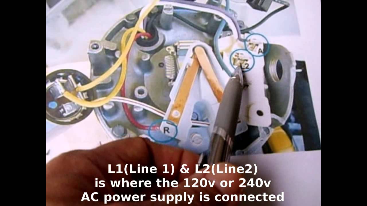
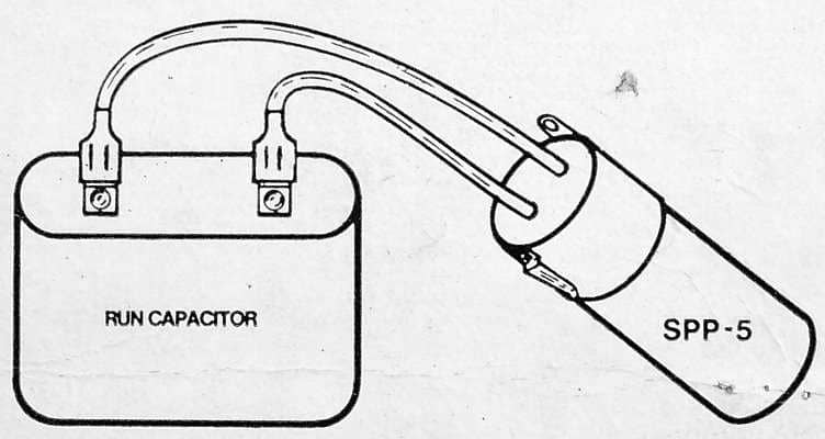
Pool pump capacitor wiring diagram. Wondering how a capacitor can be used to start a single phase motor. Step 3 push the wire terminal on the start capacitor relays common wire usually the black wire to the common terminal on the load side of the. Inspect the start capacitors wiring diagram. Most pool pumps use a 220 volt capacitor start induction run csi electric motor wired directly to a pool timer through a flexible conduit or whip. Often a stamp on the side of the relay shows the wiring diagram. The pool timer acts like an automated switch.
Variety of hayward pool pump wiring schematic. Symptoms of a bad capacitor. A wiring diagram is a streamlined traditional photographic representation of an electric circuit. You should contact and use a licensed electrician. Most pool motors require extra torque to get the motor up to speed. It reveals the parts of the circuit as streamlined shapes as well as the power and also signal links in between the tools.
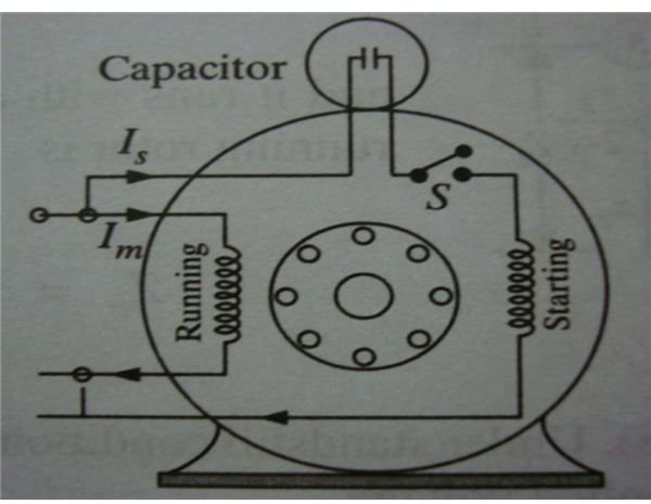
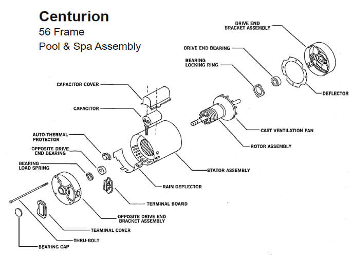
Drive end bearing locked to limit shaft endplay. This video guide will help you check the capacitor. When you turn on your pump and the motor produces a humming sound the motor may be frozen so that it wont turn or you may have a bad capacitor. Also read about the speed torque characteristics of these motors along with its different types. It reveals the components of the circuit as streamlined shapes and also the power and signal links in between the tools. Click here to view a capacitor start motor circuit diagram for starting a single phase motor.
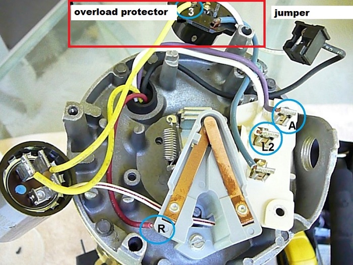
Brackets resist corrosion from pool chemicals. Many pool pump motors use a thermal overload protector that prevents the motors windings from overheating. Easy connect terminal board is designed with screw post line terminals. A failed capacitor will prevent the motor from turning over. A wiring diagram is a simplified standard photographic depiction of an electrical circuit. Variety of hayward pool pump wiring diagram.
Start capacitors are usually located at the back of the motor and the run capacitor is located at the top of the motor. Is your pool pump motor humming but not turning on. The diagram identifies the capacitor and relays wire color and the wires function. Learn how a capacitor start induction run motor is capable of producing twice as much torque of a split phase motor.
Gallery of Pool Pump Capacitor Wiring Diagram