But it does tend to become more complex. The below list shows the basic types of wiring connections available for di do ai ao signals.
Basic Electrical Design Of A Plc Panel Wiring Diagrams Eep
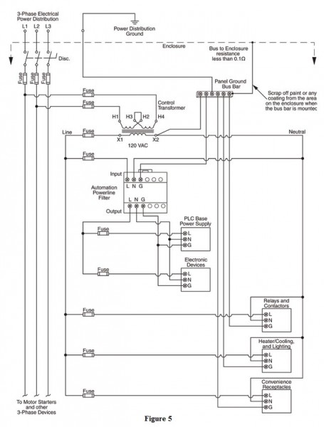
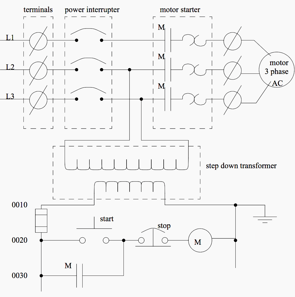
Plc panel wiring diagram. Fuse 06fu feeds our circuit. Figure 5 below shows a schematic diagram for a plc based motor control system similar to the previous motor control example. April 28 2019 by larry a. Electrical wiring diagrams of a plc panel. November 6 2018 by larry a. Hot electrically live wire 06a is passed to the field junction box fjb as one wire in a multi conductor cable.
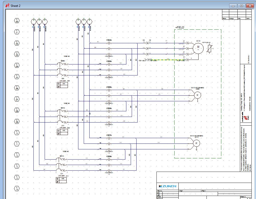
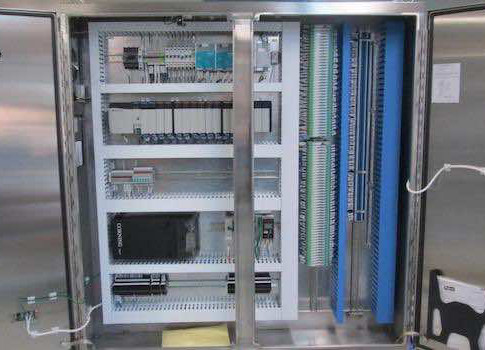
A wiring diagram is a simplified conventional photographic representation of an electric circuit. An industrial control cabinet with wire runs terminal strip buttons on plc panel front etc. Wellborn collection of plc wiring diagram guide. The electrical design for each machine must include at least the following components. Fuse 03fu is the main disconnect fuse while the remaining fuses are distribution fuses. In an industrial setting a plc is not simply plugged into a wall socket.
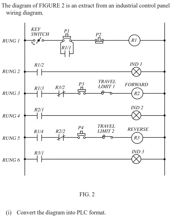
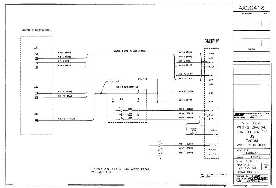
Wiring diagrams of plc and dcs systems. A wiring diagram is a streamlined traditional pictorial depiction of an electric circuit. Transformers to step down ac supply voltages to lower levels. When including a plc in the ladder diagram still remains. The main power feed is brought to a marshalling panel where the power is split feeding multiple fused circuits. It shows the elements of the circuit as streamlined shapes as well as the power as well as signal connections in between the tools.
Plc and scada training courses. Wellborn assortment of plc panel wiring diagram pdf. Digital input di signals. It shows the parts of the circuit as streamlined shapes and also the power as well as signal connections in between the devices. Note that these diagrams are without a barrier or isolator fuses and surge protector for keeping it very simple and understandable.
Gallery of Plc Panel Wiring Diagram