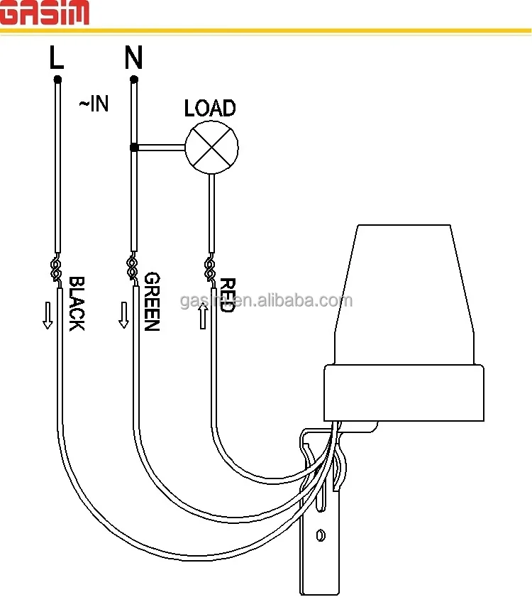
Step 6 connect the wires in the following order. Otherwise the structure will not work as it should be.
Snr 100wf Photocell Wiring Diagram Ceilingfanswitch Com
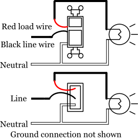
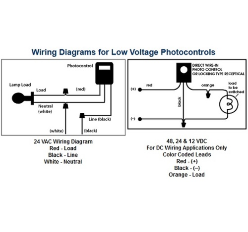
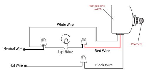
Photocell switch wiring diagram. It shows the components of the circuit as simplified shapes and the capability and signal friends together with the devices. Wiring diagram for photocell switch wiring diagram is a simplified satisfactory pictorial representation of an electrical circuit. With this sort of an illustrative manual you will be able to troubleshoot avoid and complete your tasks with ease. Here is a picture gallery about photocell switch wiring diagram complete with the description of the image please find the image you need. The black line wire connects to line voltage from the panel the red load wire connects to the light s the white neutral wire connects to the neutral wires of the circuit. Photocell and timer wiring diagram 1 photocell and timer wiring photocell and timer switch wires each have a line black load red neutral white and ground green.
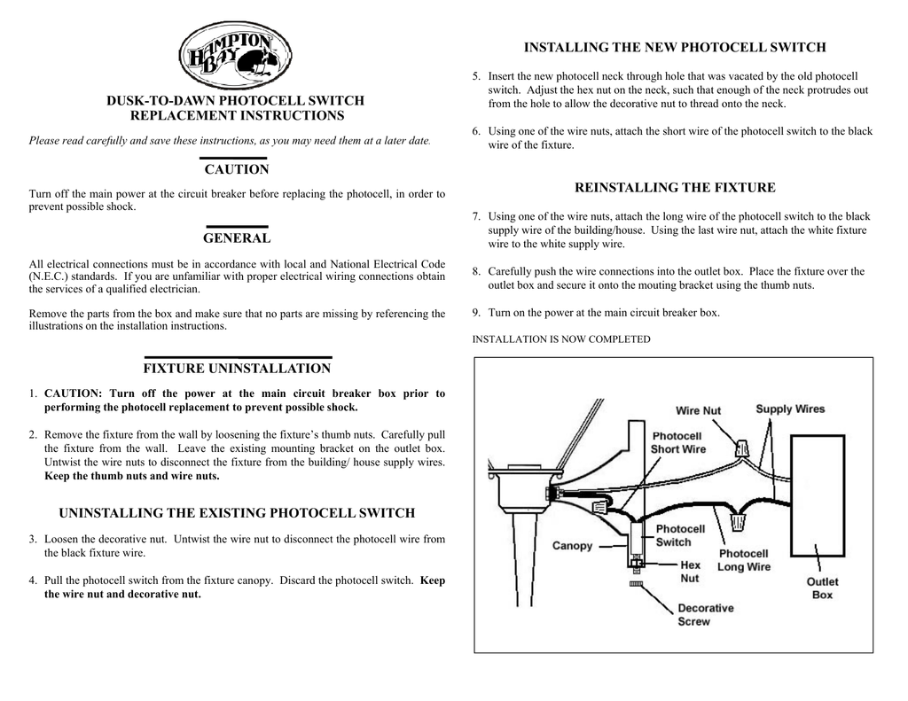
Short version how what and where to do with the three wires on that photocell you want to use to automatically turn your lights on at dusk and off at dawn. The red wire is the switch wire coming from the photocell. How to wire motion sensor occupancy sensors with photocell switch wiring diagram image size 600 x 417 px and to view image details please click the image. Photocell wiring diagram 220v photocell wiring diagram came photocell wiring diagram gate photocell wiring diagram every electrical arrangement consists of various different components. Photocell wiring diagram youll need an extensive professional and easy to comprehend wiring diagram. Wellborn assortment of photocell switch wiring diagram.
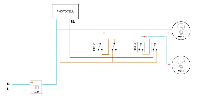
How to wire a photocell switch in a lighting installation as shown above the load wire lo goes to the lighting installations connected in series while the neutral n wire through a breaker is looped to all the lights. If the lights remain on with the switch off highly doubtful you have something messed up. It shows the elements of the circuit as simplified forms and the power and also signal links between the devices. Not merely will it assist you to achieve your required final results faster but in addition make the whole procedure easier for everybody. Use the wire pliers and twist together all three of the white neutral wires covering the bare copper ends with a wire nut. Turn the light switch off first to make sure the lights do in fact turn off to isolate the problem to the wiring at the photocell or the photocell itself.
A wiring diagram is a simplified standard photographic representation of an electrical circuit. Each component ought to be set and linked to other parts in specific manner. The light switch should always remain in the on position for the photocell to operate automatically. If you would like to see more about the. The supply line through a breaker supplies the photocell electrical power. April 3 2019 by larry a.
The white wire is the switchs neutral wire and the black is the main power going into the photocell switch.
Gallery of Photocell Switch Wiring Diagram