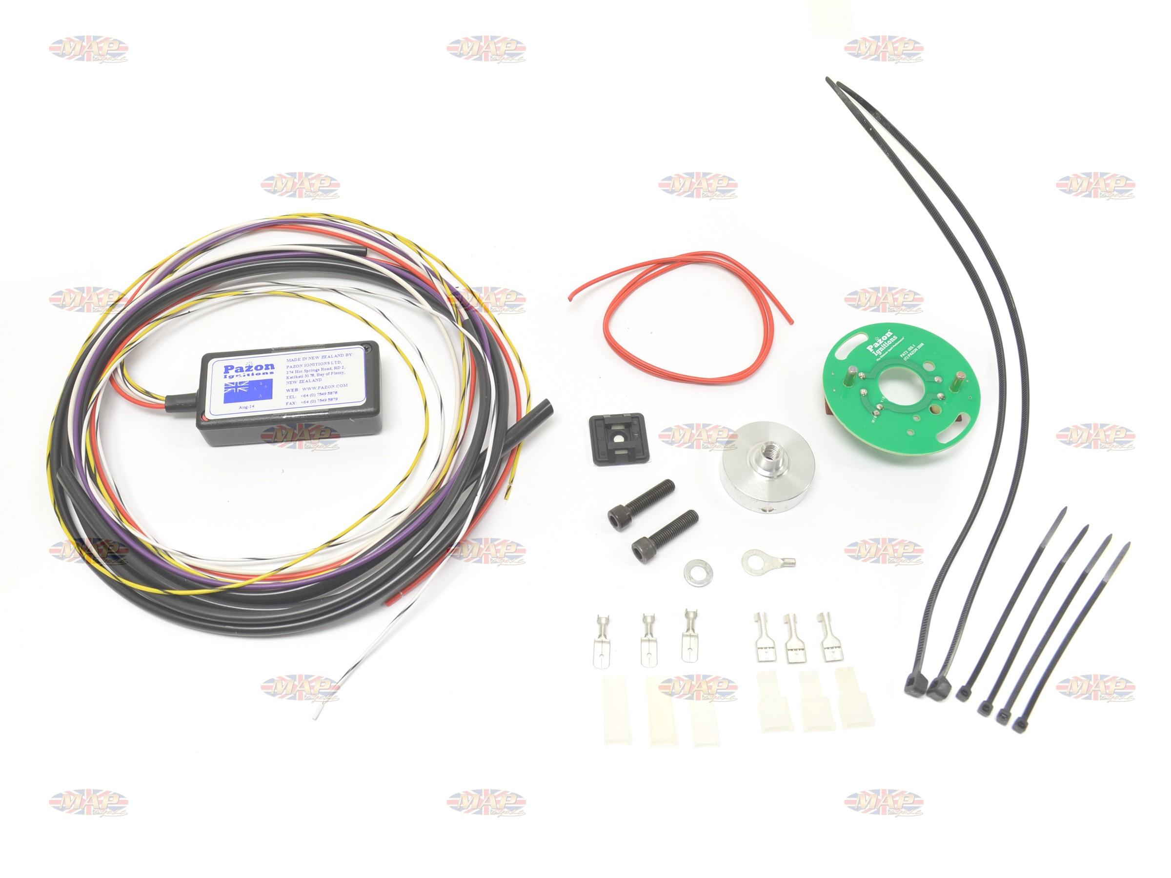
Photos wiring diagrams and advance curves. An east german commuter but ignition by pazon or some such would be impressive note.
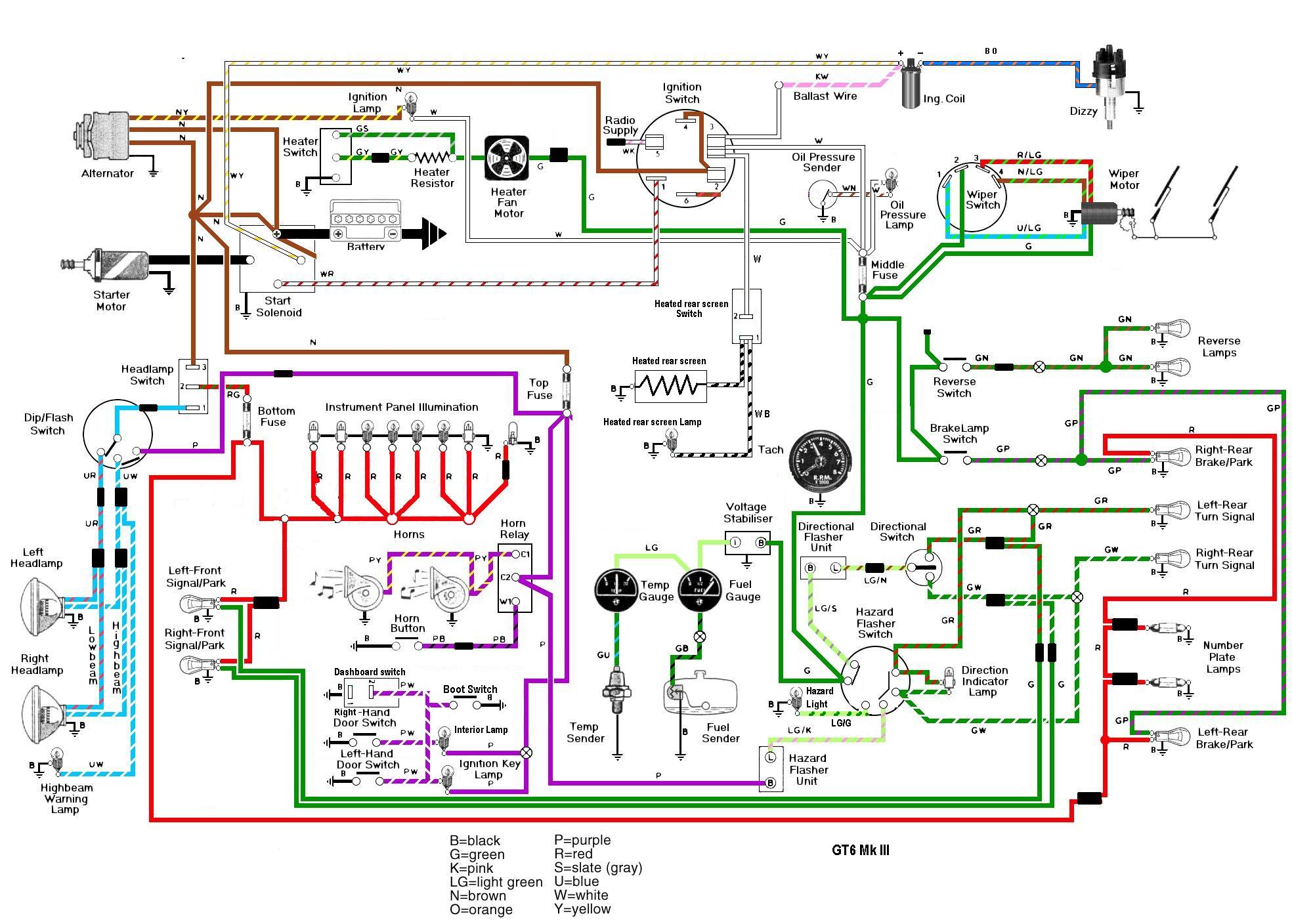
Can Anyone Doublecheck This Diagram For Me
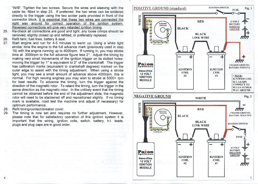
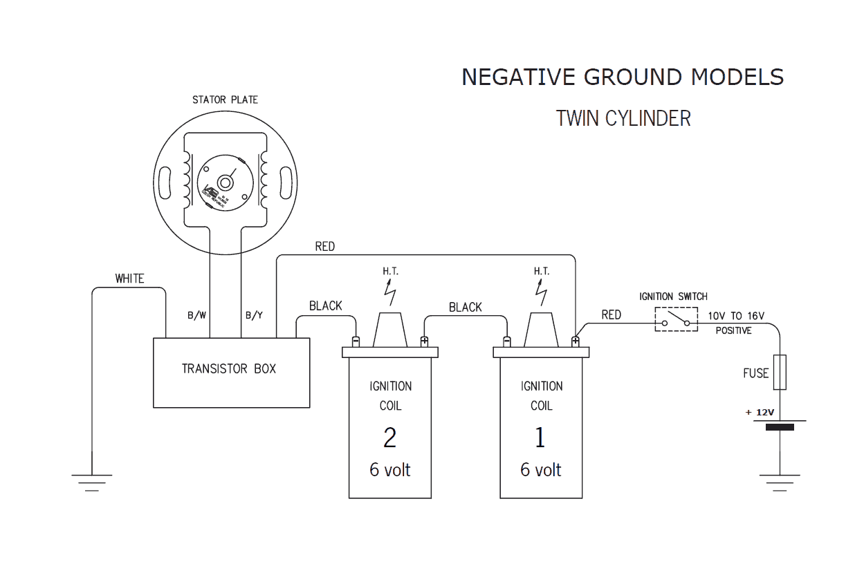
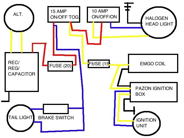
Pazon ignition wiring diagram. The color coding of the wiring is simple. Ignition spares spares are defined as items not purchased as part of a complete ignition system. If using a dual output coil the link wire is not required. The white this is the negative feed to the pazon. Youll note in the wiring diagrams below that the ballast resistor and condensers have been removed as part of the conversion to electronic ignition. The black this is the negative supply from the pazon to the coils.
The red this is the positive feed to the pazon and is usually picked up from the red wire that goes to the coil positive terminal. Pazon warrants to the original purchaser that the pazon ignition system be free from defects. In workmanship parts under normal use for a period of 7½ years from date of purchase. Take the violet wire from the ignition module cut to length and fit a female crimp connector and insulator to the end of the wire. Connect the violet wire to the negative terminal of coil1. The color coding of the wiring is simple.
This draws a similar current to the ignition system and gives a visual indication of available power. Switch the ignition on the. Positive ground system wiring diagram. The mz was fitted with a negative earth type energy booster. A better way to test for a good power feed to the ignition module is to use a stop lamp or indicator bulb in addition to the test meter. Connect the test bulb between the frame ground and the ignition feed wire.
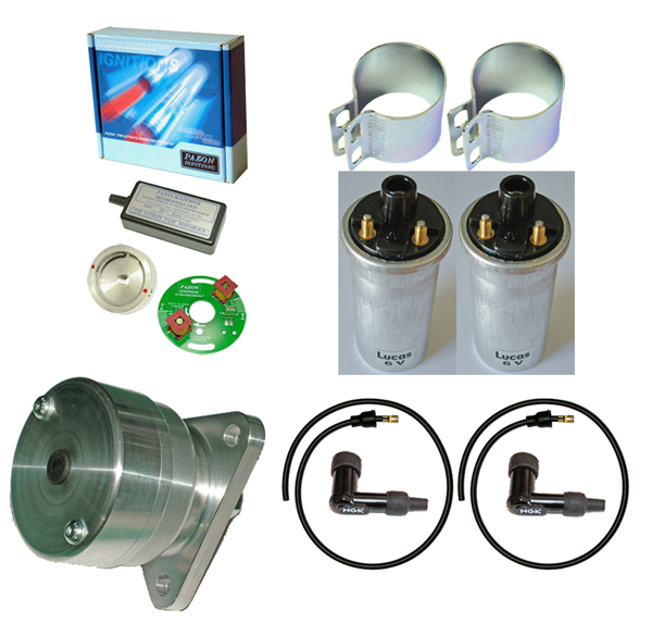
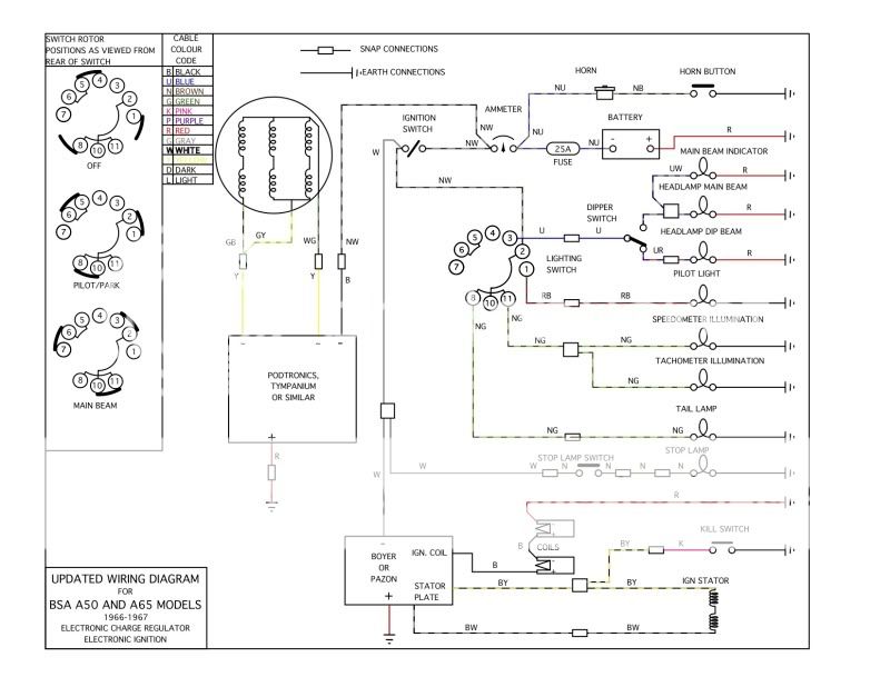
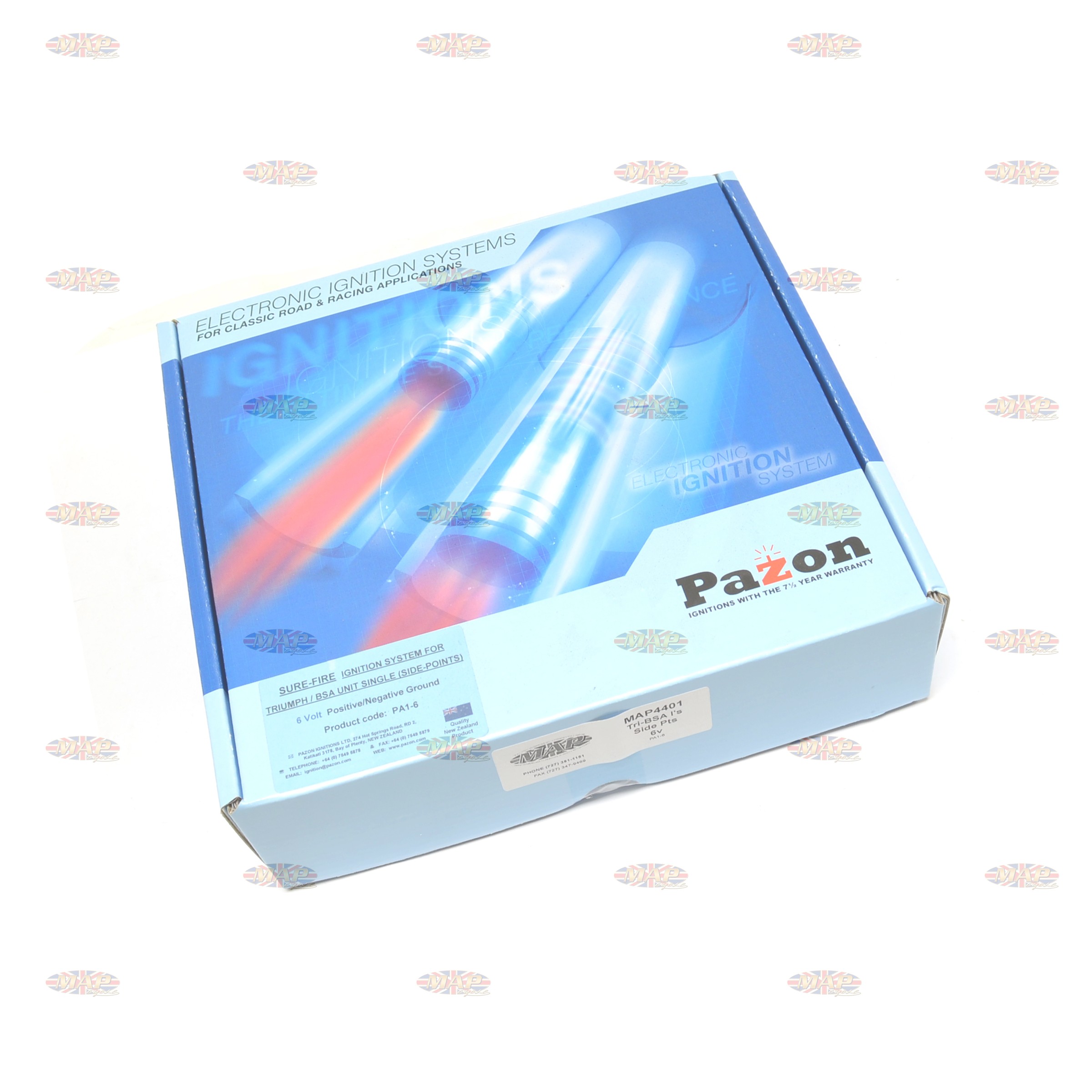
Sure fire advance curves triumphbsanorton twins excellent after sales technical support is available by email fax and phone 0900 1700 mon fri. In the wiring diagrams. The pazon sure fire ignition system is the worry free solution to keeping your classic bike on the road. Fitting instructions you can actually read. The red this is the positive feed to the pazon and is usually picked up from the red wire that goes to the coil positive terminal. Youll note in the wiring diagrams below that the ballast resistor and condensers have been removed as part of the conversion to electronic ignition.
Every pazon system comes complete with a comprehensive full colour installation booklet with step by step instructions photos and wiring diagrams.
Gallery of Pazon Ignition Wiring Diagram