5614 hollins road roanoke virginia 24019. 8 am 730 pm est.

Toa Electronics Inc Paging Mic
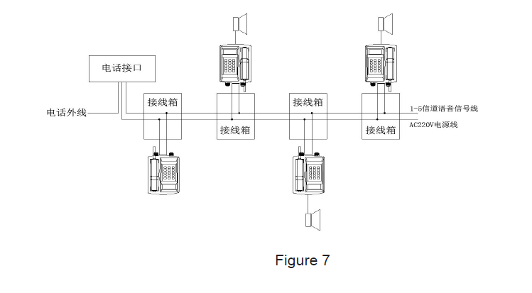
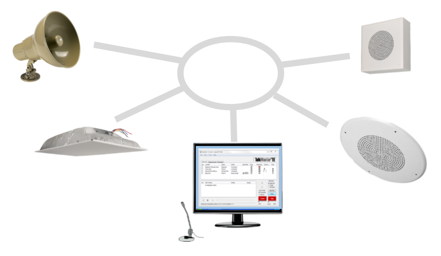
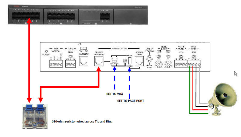
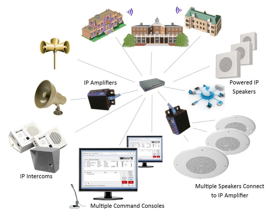
Paging system wiring diagram. Some paging equipment such as bogens pcm2000 uti1 and uti312 paging interfaces include a test tone that is sent to all speakers in the system so installers can check the. Variety of bogen paging system wiring diagram. System covers an area is to test it. Sound adjust ments or additional speakers may be needed. Page system cabling guidelines cat 56. One way all call to all speakers available.
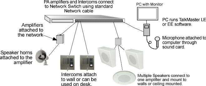
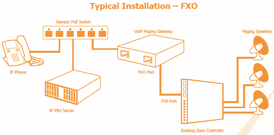
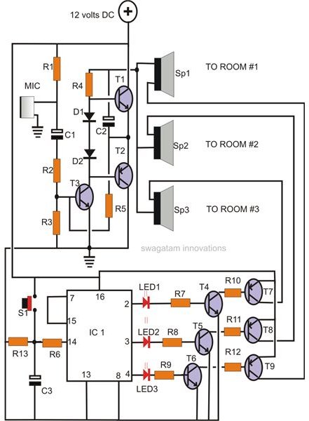
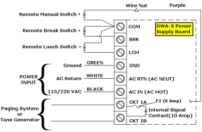
Collection of bogen paging system wiring diagram. It shows the components of the circuit as simplified forms and also the power and also signal links in between the tools. A wiring diagram is a simplified conventional pictorial representation of an electric circuit. Overhead paging system installation guide and components you can connect your office phone system to an overhead loud speakers paging system to make office announcements or play background music. Never install a paging system and leave the site without testing it. An extra interface device is needed in order to create the connection.
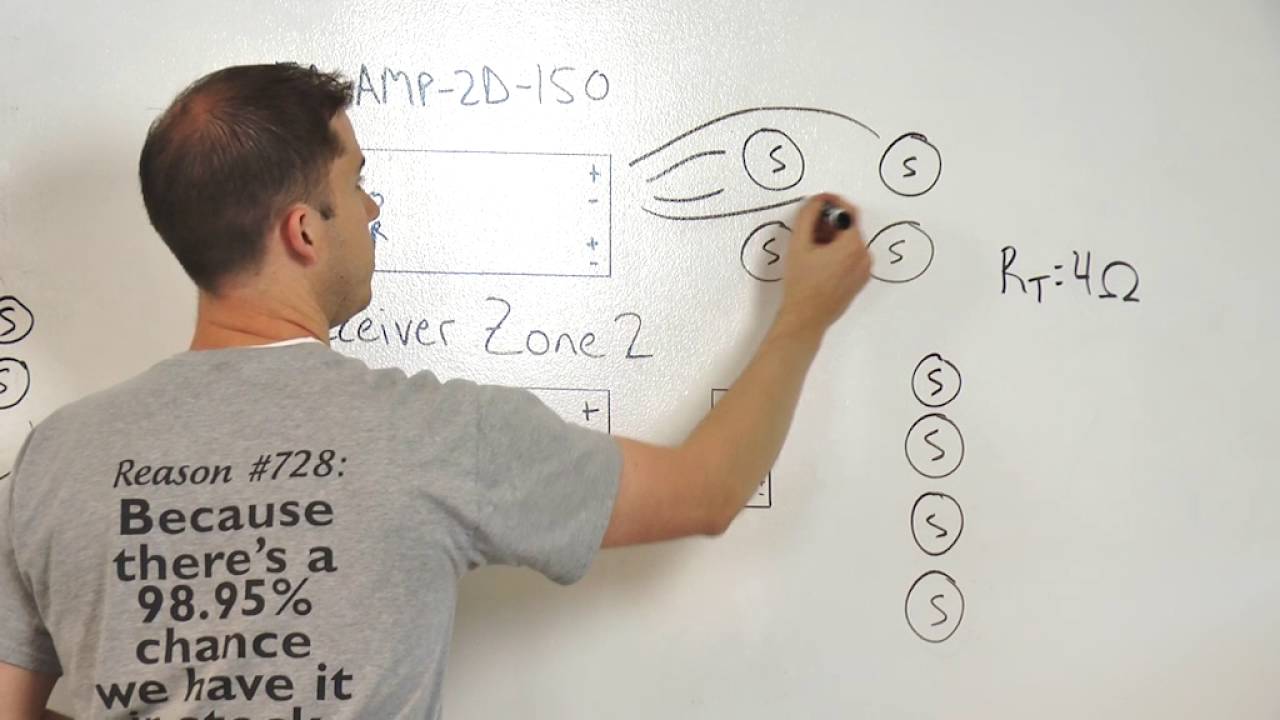
A wiring diagram is a streamlined conventional photographic depiction of an electrical circuit. V 1080 wiring diagram 801 pdf glossary. One way paging system block diagram figure 1 features 1 3 6 and 24 expandable with v 2925a in 24 zone increments for up to 96 zone page control units available. It shows the parts of the circuit as streamlined forms and also the power and signal connections in between the devices. Loudspeaker paging wiring diagram. Volume controls and amplifiers in each speaker.
Gallery of Paging System Wiring Diagram