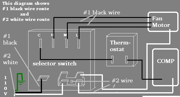
How to wire an air conditioner for control 5 wires. Package ac wiring diagram unit best of.

Package Ac Wiring Diagram Schematics Alpa Immo Ak De
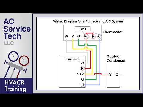
Package ac unit wiring diagram. Condenser airflow should not be restricted. Split air conditioner wiring diagram. Goodman ac unit wiring diagram collection goodman gas pack wiring diagram data beautiful heat pump package. Red wire for air conditioner control power hot. A wiring diagram is a streamlined standard pictorial representation of an electric circuit. G terminal to the green wire.
Unit should be installed on roof curb and leveled. Carrier air conditioning unit wiring diagram refrence goodman air. Collection of split air conditioner wiring diagram. Package ac controll wiring diagram with thermostat rywg wire connection everything learn practically. It reveals the components of the circuit as streamlined shapes and the power and also signal links between the gadgets. Air conditioner thermostat wiring diagram sample.
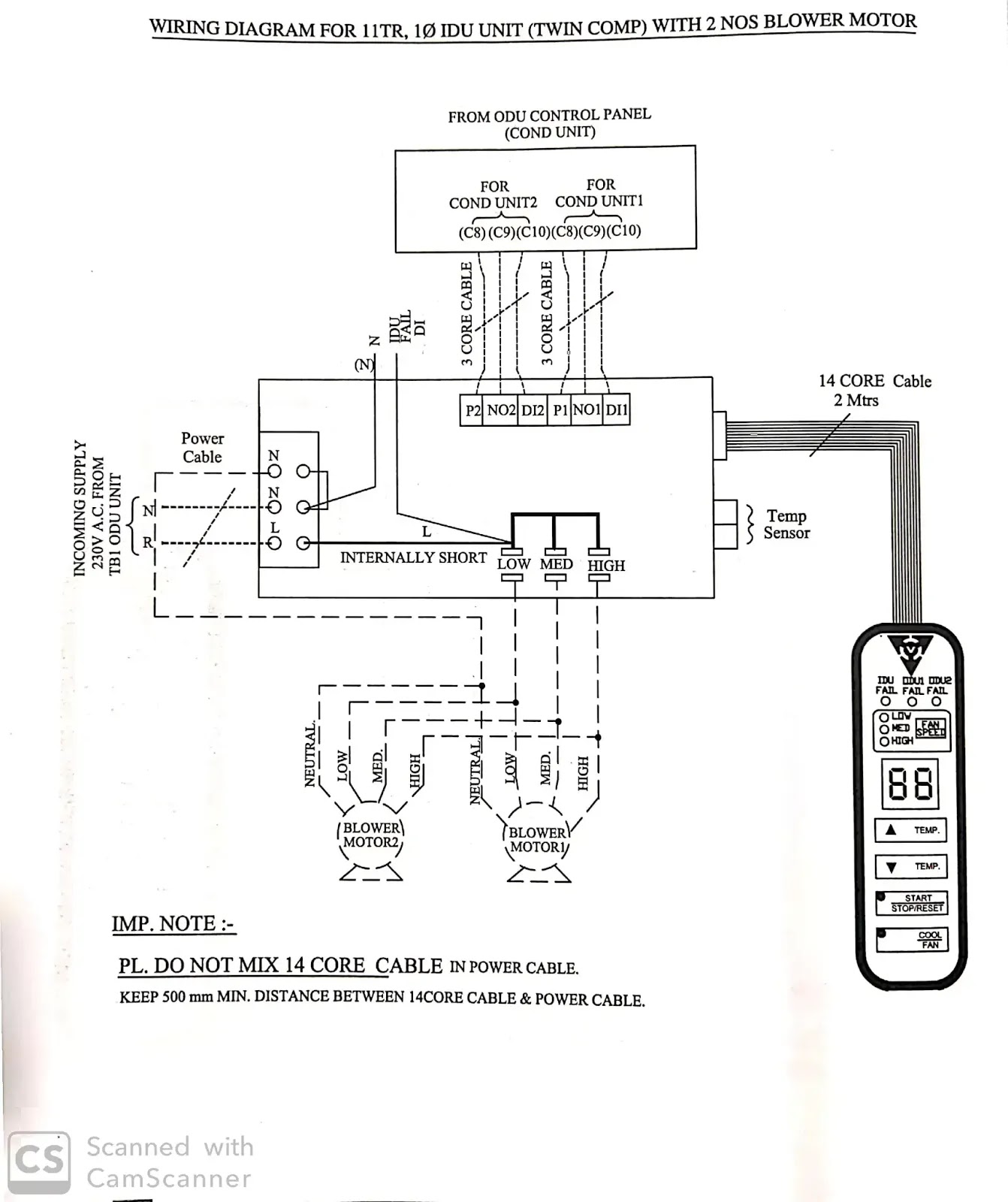
After that the main power cord of the split air conditioning unit is connected to this disconnecting means from one side the other side is connected to the terminal box in the indoor unit see fig9 or in the outdoor unit see fig10according to the manufacturers recommendations and wiring diagrams. A wiring diagram is a streamlined traditional pictorial representation of an electric circuit. Breakdown of colors and terminals thermostat wiring diagram for ac unit. Number 006 024 winter start 4 evaporator defrost thermostat 5 temp. Electrical wiring diagrams for air conditioning systems part one. Y terminal to the yellow wire.
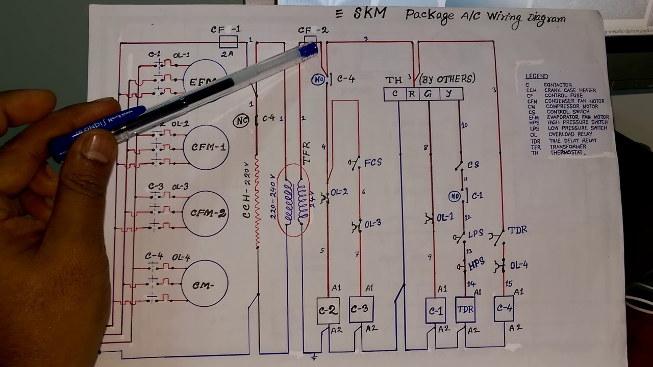
Fig6 is a typical installation diagram for a residential cooling system. Wellborn collection of goodman ac unit wiring diagram. C terminal to the blue wire. Or simply schematics a typical schematic of a packaged air conditioner is shown in fig3. Skm packaged air conditioning units control wiring diagram in hindi part 1. Payne package unit wiring diagram luxury carrier package unit.
August 24 2018 by larry a. R terminal for the red wire. W terminal to the white wire. On applications when a roof curb is used the unit must be positioned on the curb so the front of the unit is tight against the curb. And very rarely will it include any internal wiring of the unit. Refrigeration and air conditioning heating and air conditioning hvac filters electrical circuit diagram hvac repair flavio jab refrigerator conditioner.
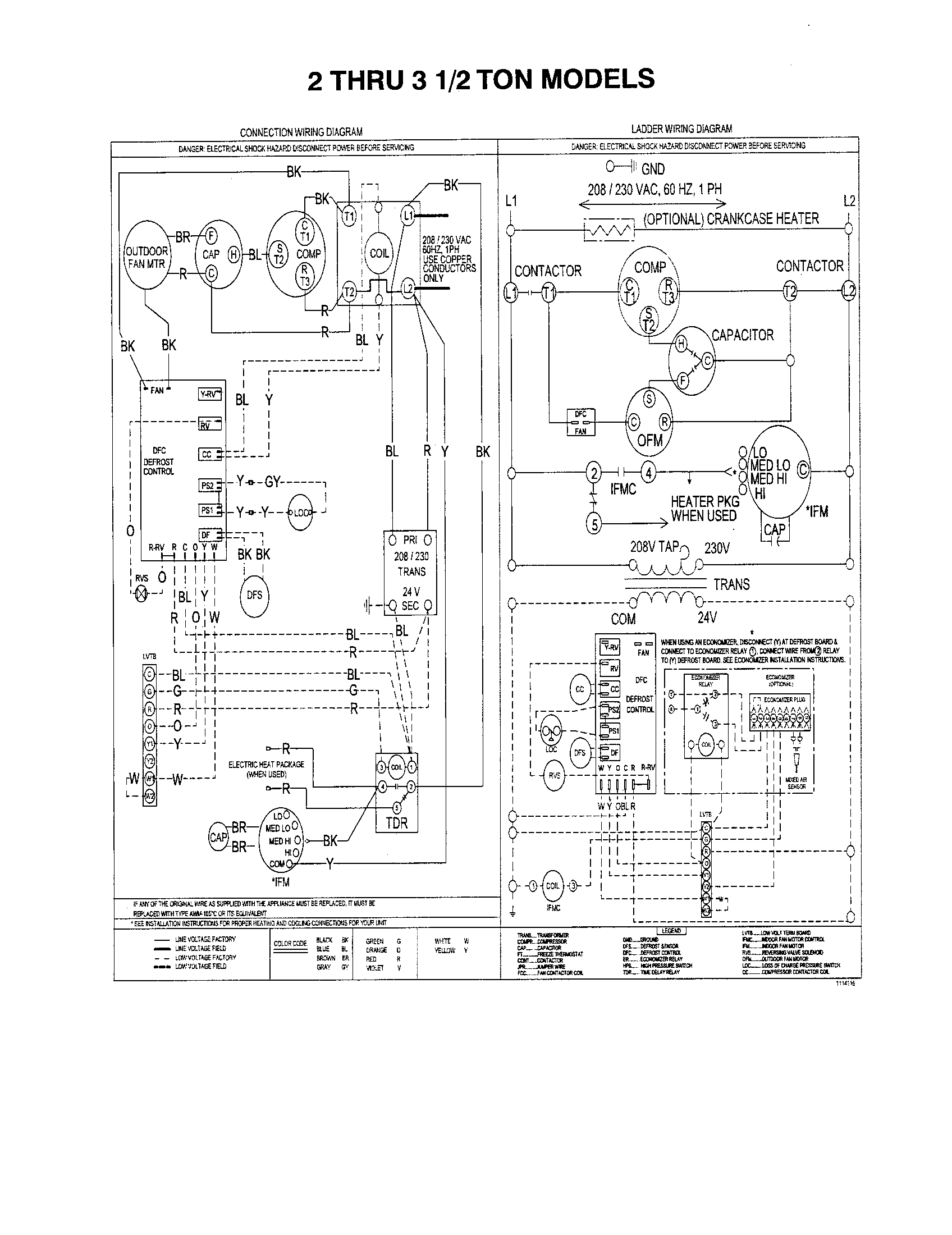
It reveals the components of the circuit as simplified shapes and the power and also signal links in between the devices. The weight of unit. Number 006 008 208230 3 60 460 3 60 11720011 c 1 575 3 60 012 208230 3 60 014 460 3 60 11720960 b 2 016 575 3 60 024 208230 3 60 460 3 60 1172007 c 3 575 3 60 accessory wiring unit 50byn accessory description fig. For ground level installation a level slab should be used. Wiring diagrams index unit 50byn v ph hz label diagram fig.
Gallery of Package Ac Unit Wiring Diagram