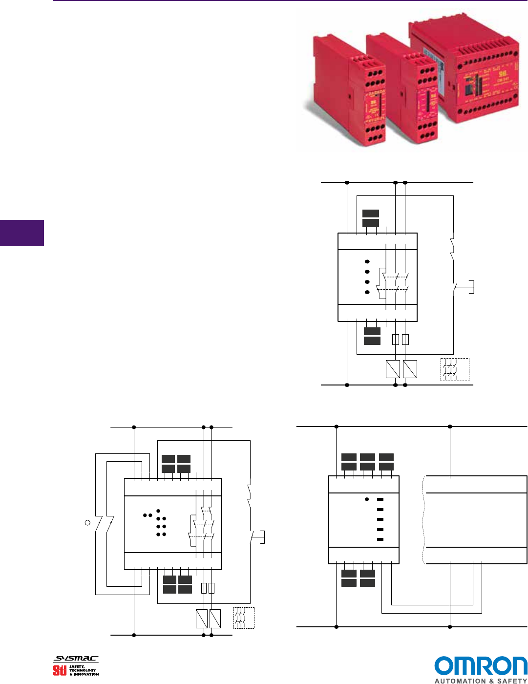
It shows the components of the circuit as streamlined shapes and also the power and also signal connections in between the devices. By measuring flow of current the safety relay checks for welded contact sets and wire breaks.

G9sp Safety Controller Basic Operations
Omron safety relay wiring diagram. When t23 i s being used please open t21 and t22. Check the wiring by comparing it to the wiring diagrams. Terminal t23 terminal t23 is used for 2 channel input with a positive common when connecting a safety sensor with a pnp output. Collection of omron safety relay wiring diagram. A wiring diagram is a simplified standard photographic depiction of an electrical circuit. As stipulated by standards omron safety components are equipped with functions such as direct opening mechanisms for switches and forced guide contact mechanisms.
For 1 channel i nput short circuit t12 t23 before use. Omron safety relay wiring diagram gallery. Safety relays are used to build safety circuits for equipment and facilities. A control system cannot be constructed using only. With over 30 years of service experience and a portfolio of industry leading technology our world class team can help you solve problems and sharpen your competitive edge. It shows the elements of the circuit as simplified forms as well as the power and signal links between the gadgets.
A wiring diagram is a simplified traditional pictorial representation of an electric circuit. Safety output contacts 13 14 23 24 33 34. 4 the role of safety components. Wiring of inputs and outputs 1. These functions are designed to operate correctly within the control system in which they are used. Variety of omron safety relay wiring diagram.
This is all done with timing. Safety relays have a forced guided mechanism that enables detecting contact welding. Omrons comprehensive lineup of machine safety components from safety logic controllers and light curtains to door switches and stop devices provide everything you need to protect your team and factory from operational hazards. A safety relay detects wire breaks and faulty contactorsactuators by sending out electrical pulses through the wiring. 6550 dumbarton circle fremont ca 94555 3605 usa. Sr103am dual channel safety monitoring relay instruction sheet.
Check the safety switch used for correct function and. Timing is the other fault detection method safety relays use. Safety components the safety components that are used in these circuit examples are equipped with functions such as a direct opening mechanism for switches and a forcibly guided mechanism for relays as required by standards. Safety related control systems must minimize the possibility of danger occurring even when there is a failure in the interlock device. Omron scientific technologies inc.
Gallery of Omron Safety Relay Wiring Diagram