As we have seen null modem connections are made possible through the use of a null mode cable. Serial and usb communications cables modem usb to db9 wiring diagram from usb wiring diagram topic.
Null Modem Electronic Component Png Download 1280 582
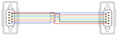
Null modem cable wiring diagram. The term db9 refers to a common connector type one of the d subminiature or d sub types of connectors. This is the simplest solution to connecting the two computers. You almost dont even need a null modem wiring diagram but if youre visual take a look at the wiring diagram on the right. See also optec. Here we have another image acheter câble série usb filaire croisé ftdi ft232r adaptateur usb. Use this cable to connect two devices equipped with serial rs 232 interface.
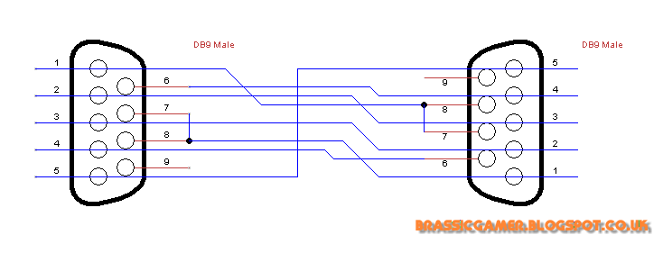
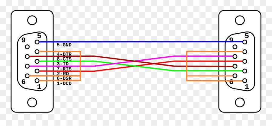
Db9 connectors are designed to work with the eiatia 232 serial interface standard which determined the function of all nine pins as a standard. Below is a very common wiring diagram for a null modem cable to interconnect two dtes eg. Lets explain it another way. The simple null modem cable and the null modem cable with loop back handshaking are useful but have no provisions for hardware flow control. The purpose of a null modem cable is to permit two rs 232 dte devices to communicate with each other without modems or other communication devices ie dces between them. The following schematic diagram show the male grey background and female black background pin numbering for db 9 connector.
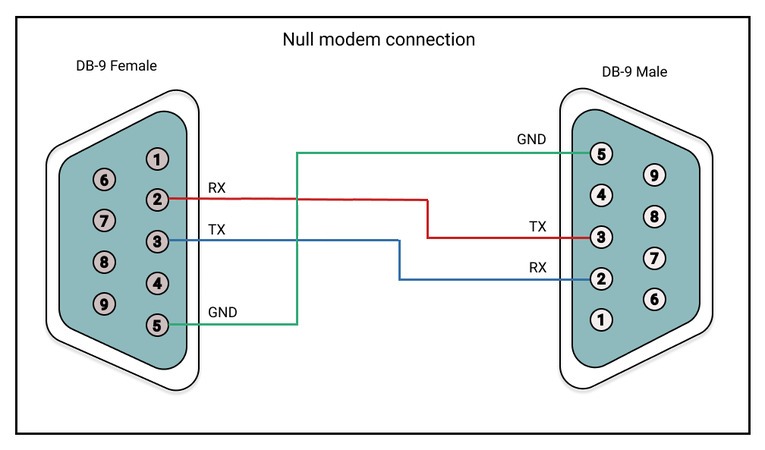
Null modem pinout to usb wiring diagram wiring library modem usb to db9 wiring diagram uploaded by yamama on tuesday february 12th 2019 in category usb wiring diagram. The cable is comprised of three lines. Two pcs providing full handshaking which works with software relying on proper assertion of the data carrier detect dcd signal. This cable may be used to connect any rs 232 equipped device to computer connect two computers via com serial port and so on. To achieve this the most obvious connection is that the td signal of one device must be connected to the rd input of the other device and vice versa. But what is a null modem cable.
The purpose of a null modem cable is to permit two rs 232 dte devices to communicate with each other without modems or other communication devices ie dces between them. De 9 null modem wiring diagram. Db 9 connector pinout null modem wiring diagram. If it is absolutely necessary that hardware flow control is used the null modem with partial handshaking can be an alternative. Rs232 null modem pinout and wiring. Transmit data to receive data in both directions thats two of the pins and ground to ground.
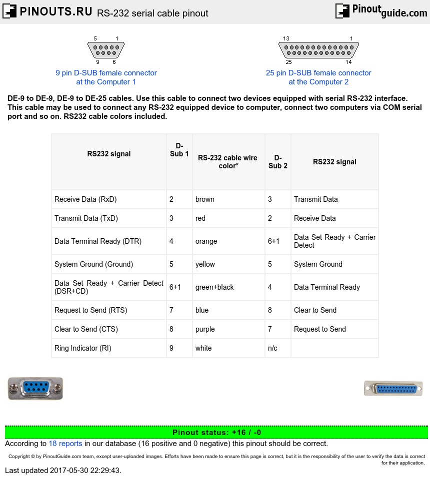
To achieve this the most obvious connection is that the td signal of one device must be connected to the rd input of the other device and vice versa. Here are the magical three pins for my 3 wire null modem cable. Pinout of null modem cables and layout of 9 pin d sub female connector and 25 pin d sub female connectorde 9 to de 9 de 9 to de 25 cables.
Gallery of Null Modem Cable Wiring Diagram