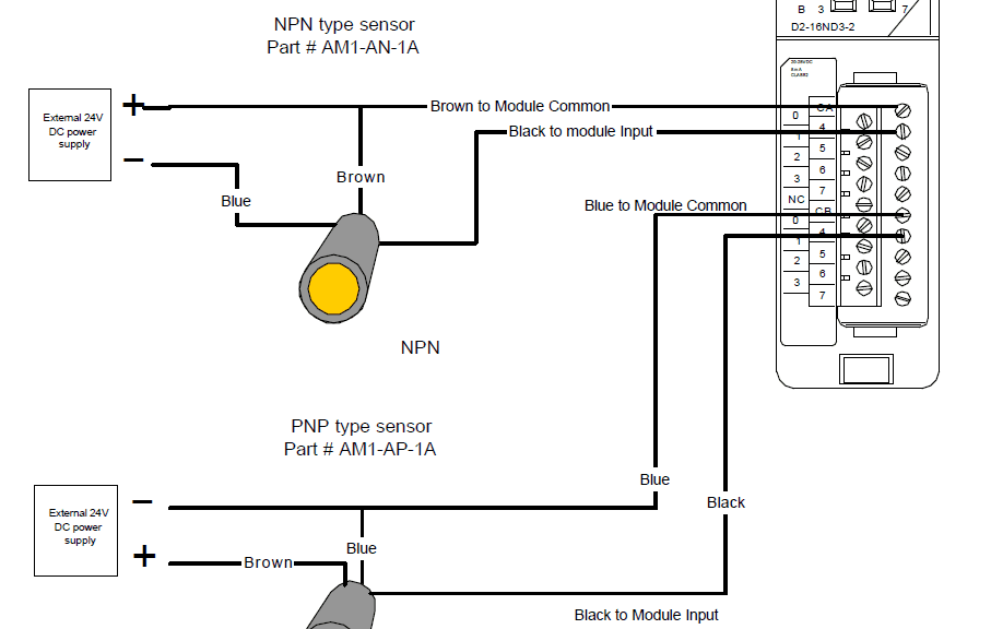
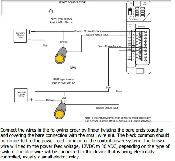
The following is a wiring diagram of an open collector npn sensor. This means that multiple sensors can be connected to an input card with all sensor negative wires to one common wire.
Ebook Implementation Products Robotics And Other Useful
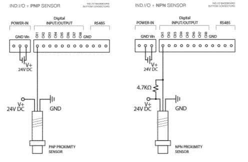
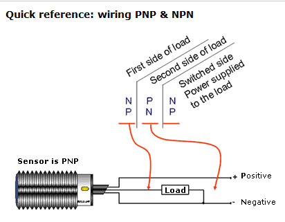
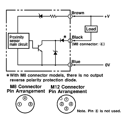
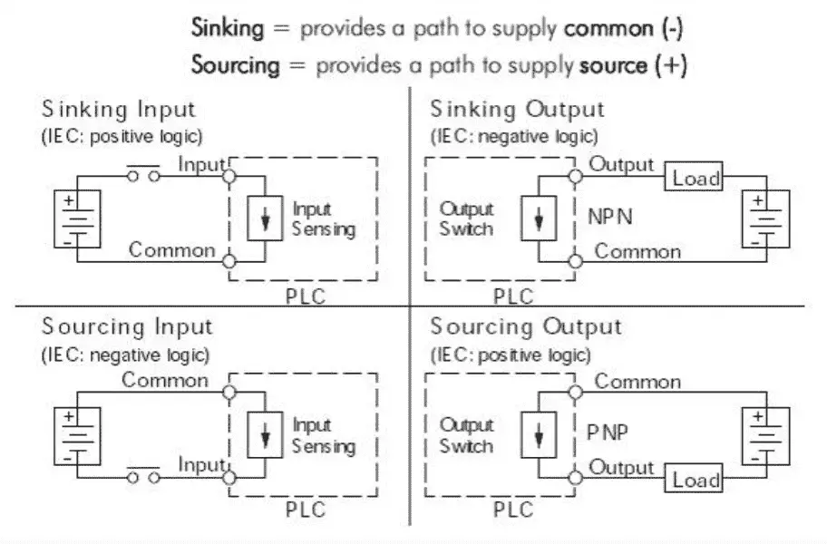
Npn proximity switch wiring diagram. Industrial sensors of all types have connection diagrams. Pnp switched positive npn switched negative switched refers to which side of the controlled load relay small indicator plc input is being switched electrically. You will notice that the load appears between the v brown and switching wire black. That means that the sensor can be wired as positive sourcing or negative sinking switch. The v brown will be attached to the common input and the switching wire black will be attached to the input number. The ck1 00 2h is an 18mm diameter npnpnp nonc.
A pnp sensor may be either no or nc as can an npn be. Two specific types of 3 wire sensors are available. When connecting to the plc the plc input acts as the load. The schematic diagram symbol for a proximity switch with mechanical contacts is the same as for a mechanical limit switch except the switch symbol is enclosed by a diamond shape indicating a powered active device. Either the load is connected to negative and the positive is switched pnp continue reading an easy way to remember pnp and npn sensor. Heres a simple way remember how to wire up a 3 wire dc pnp or npn sensor.
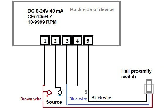
Wiring diagrams show the hook up offour sensors with npn and pnp outputs. Schematic for hall proximity switch from ebay its like a baby is drawing it in practice for laymen this diagram inappropriate. Referring to the npn wiring diagram above note that the sensor supply voltage and the high side of the load are connected to the same point and are therefore at the same voltage. Selectable output with a 12mm sensing distance. Npn sensor outputs switch in a negative fashion. The switching logic pnp or npn are not related to the supply voltage of the sensor or the operating voltage of the input.
Pnp sensor outputs switch in a positive fashion. Keep in mind that the hall probe sensor only switches when the magnet is 1 10mm awayto test the wiring run the magnet in front of the probe mthe speedometer on the led display will show. A key point to observe is that pnp and npn has nothing to do with whether the sensor is normally open no or normally closed nc ie. This wire is noted on the io modules wiring diagram. 3 wire and 4 wire dc. The difference is a result of the internal circuit design and type of transistors used.
If a switching output is strictly pnp or npn the external connection through the loadthanks for purchasing our inductive proximity limit switch kit. We will be wiring a capacitive proximity switch into the input of our click plc. Ultrasonic proximity switches sense the presence of dense matter by the reflection of sound waves. My schematic is better.
Gallery of Npn Proximity Switch Wiring Diagram