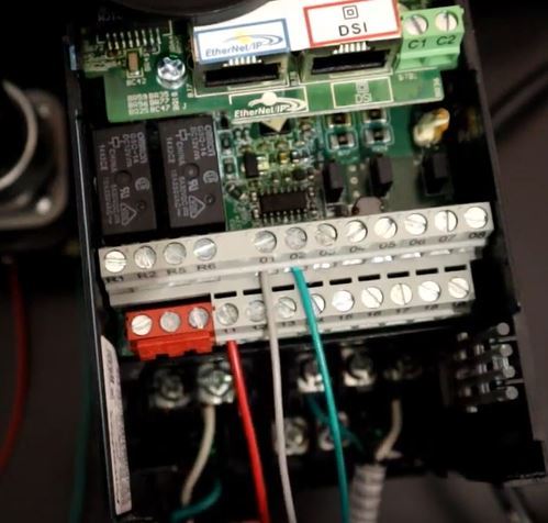
The wiring of the parallel breakout board from the output terminals to the driver digital pulse step pulse and direction lines are explained. The control wire connects to the electrical device that the limit switch is intended to control.

Cnc Wiring Schematic Toyota Down8 Zografisch Nl
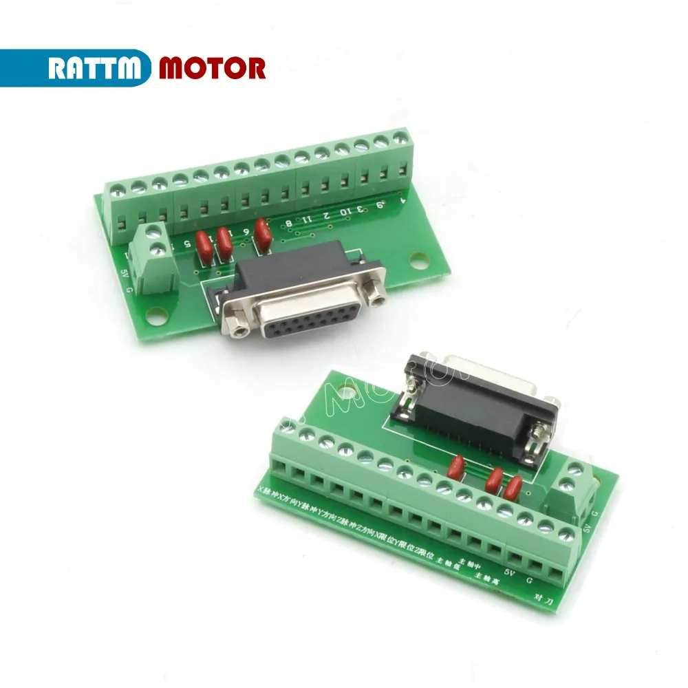
Nc studio wiring diagram. This pin is not integral to the modules operation and need not be connected. Go to the new parallel breakout board to get more information and the wiring diagram. When the internal control changes state the connection moves and. The new parallel breakout board appears a bit different but the process of wiring and testing is the same. Normally open terminal normally closed terminal and common terminal respectively. Nc or nc designates no connection.
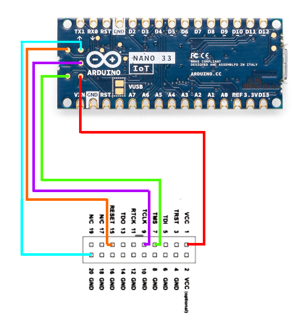
Each symbol means a single terminal itself. Tek care nc150 nc200 block wiring diagrams. Each means the combination of two contact terminals or more and is also described as make contact point break. The 800 series family of io is obsolete. Begingroup this is a circuit diagram for a development board that the chip is mounted on. The nc or nc terminals are normally isolated from the modules circuitry.
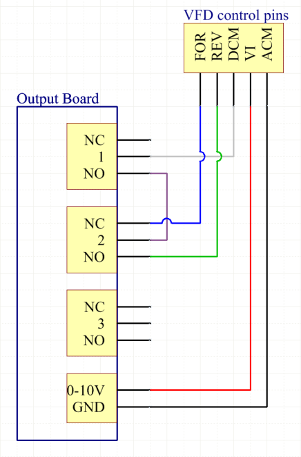
In pdf format tek care nc150 nc200 block wiring diagrams from il380. This resulted in multiple feedback loops where one signal left a device and then came right back to or through that same device again. It may very well be that thats what the nc is referring to in the pdf i am referencing but presumably it is connected to circuitry inside the esp8266. 3ø wiring diagrams 1ø wiring diagrams diagram er9 m 3 1 5 9 3 7 11 low speed high speed u1 v1 w1 w2 u2 v2 tk tk thermal overloads two speed stardelta motor switch m 3 0 10v 20v 415v ac 4 20ma outp uts diagram ic2 m 1 240v ac 0 10v outp ut diagram ic3 m 1 0 10v 4 20ma 240v ac outp uts these diagrams are current at the time of publication. The drawing shows top section above terminals the internal connections nc is without being energized connecting to c common. Step 4 insert the exposed conductor of the control wire into the no or the nc terminal and secure it by tightening the terminal retention screw with a screwdriver.
Bad studio wiring he also and this was the ultimate culprit for his woes was using the built in microphone preampinput on the mixer to plug in his microphone insert dramatic danger music here. Completely separate from general power and light wiring all technical equipment associated with broadcasting such as control room on air studio 1 on air studio 2 news room production room recording studio on air digital audio delivery computers associated file servers studio to transmitter link transmitter etc should all feed from a common. Please consider alternatives offered in the quantum or bmx families of io. On the other hand contact point a contact point b and contact point c represent contact structures. Endgroup octopus dec 23 15 at 234.
Gallery of Nc Studio Wiring Diagram