Stamford as480 automatic voltage regulator. Stamford mx321 automatic voltage regulator.

Sx460 Avr Manual Pdf لم يسبق له مثيل الصور Tier3 Xyz
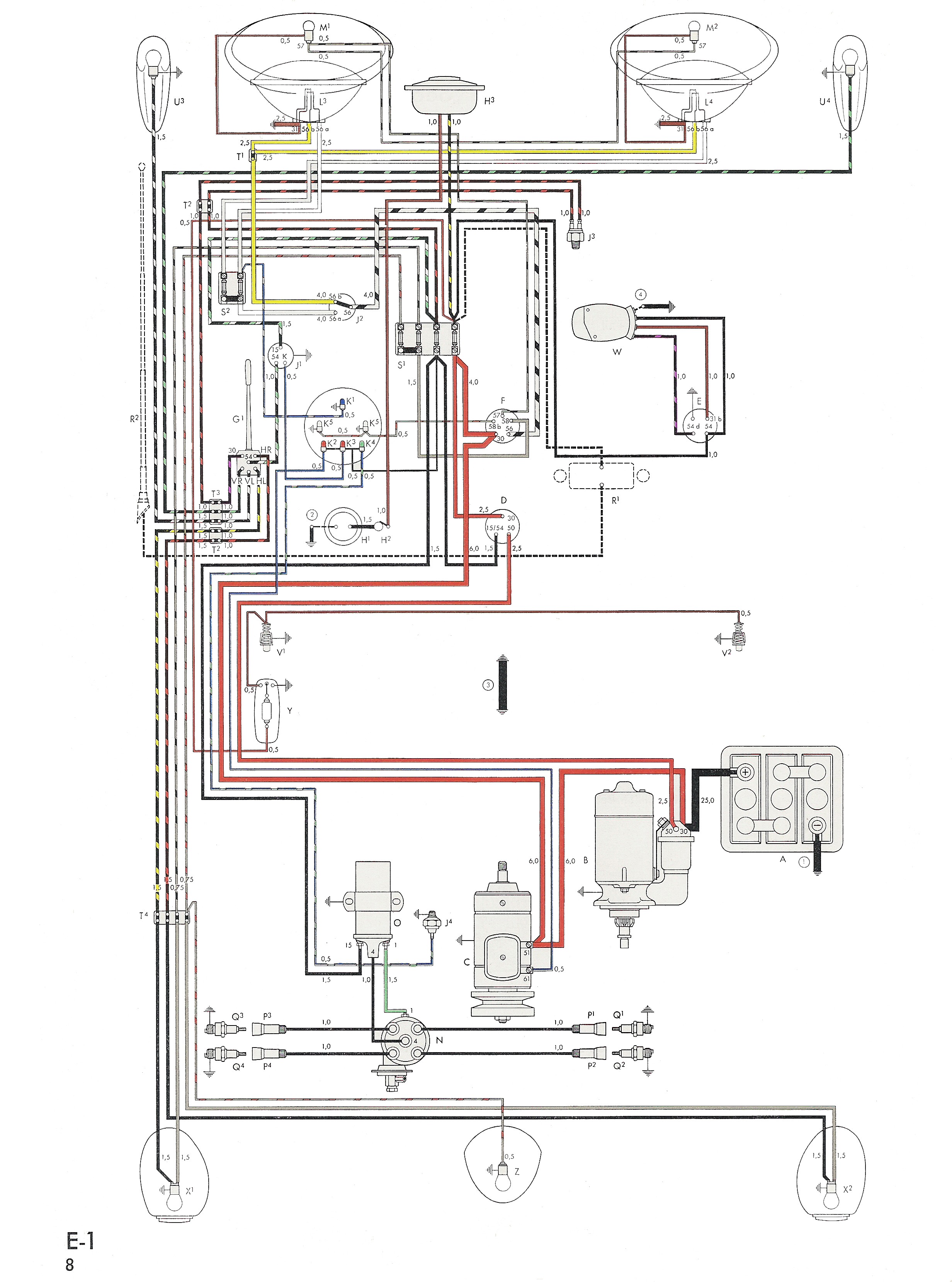
Mx321 avr wiring diagram pdf. The droop adjustment is normally preset in the works to give 5 voltage droop at full load zero power factors. Stamford mx341 automatic voltage regulator. Obscured by the customers wiring or other fittings. Refer to alternator wiring diagram for connection details. Mx321 automatic voltage regulator avr for cummins 1250kva generators. Danger live electrical conductors live electrical conductors at output avr and avr accessory terminals and avr heat sink can cause serious injury or death by electric shock and burns.
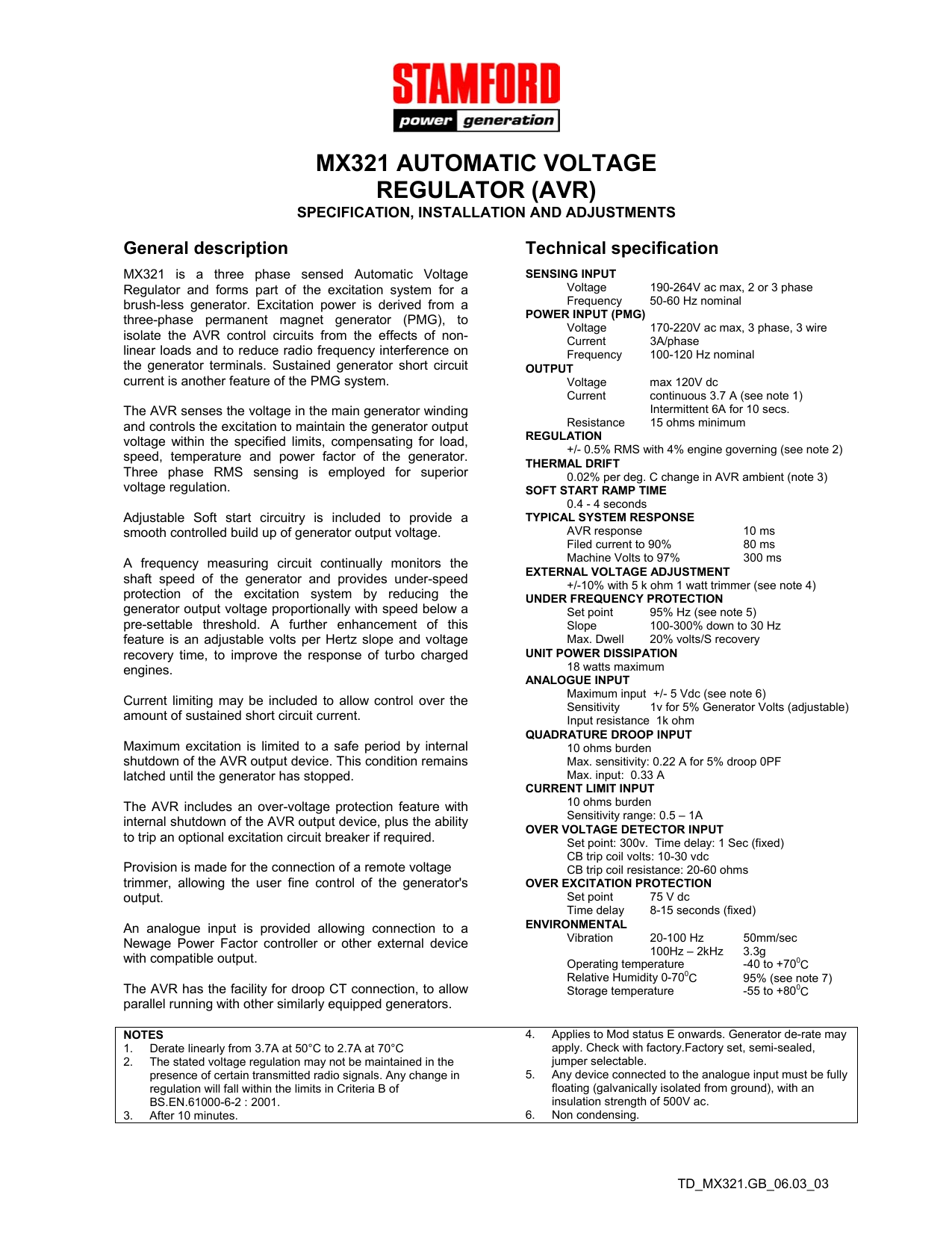
Control function turn potentiometer clockwise to. Stamford as540 automatic voltage regulator. Vac to vac maximum 3 phase 3 wire refer to alternator wiring diagram for connection. Red capacitor generator circuit diagram avr mx mx is a three phase sensed automatic voltage regulator and forms part of the excitation system for a brush less generator. Fitting and operating refer to generator wiring diagram for connection details. All stamford generators are supplied with a declaration of incorporation for the.
Refer to diagram in the back of this manual to determine wiring. Mx automatic voltage regulator avr. Excitation power is derived from a three phase permanent magnet generator pmg to isolate the avr control circuits from the effects of non linear loads and to reduce radio frequency interference on the generator terminals. Mx automatic voltage regulator avr specification controls and accessories voltage. Mx321 is a three phase sensed automatic voltage regulator and forms part of the excitation system for a brush less generator. The surface in the area where a label is to be stuck must be flat.
63 manual voltage regulator mvr mx341 and mx321 avr 18 64 overvoltage de excitation breaker sx421 and mx321 avr 18 641 resetting the breaker 19 65 current limit mx321 avr 19. Is connected to s1 s2 on the avr see generator wiring diagram for details. Is connected to s1 s2 on the avr see generator wiring diagram for details. Clockwise increases the amount of ct. Is available as an option using either the mx or mx avr. Power factor dependent signal for the avr.
A043y701 issue 2 5 ref. Signal injected into the avr and increases the droop with lagging. Signal injected into the avr and increases the droop with lagging power factor cos 0. Clockwise increases the amount of ct. The droop adjustment is normally preset in the works to give 5 voltage droop at full load zero power factor. Mx321 avr controls 6 a043y701 issue 2 32 initial avr setup notice the avr must be setup only by authorised trained service engineers.
Gallery of Mx321 Avr Wiring Diagram Pdf