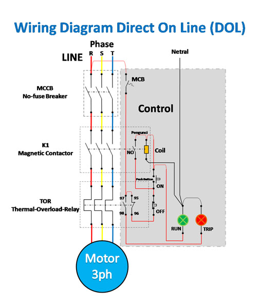
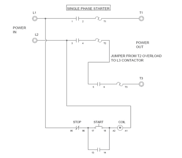
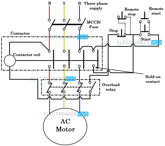
Figure 1 is a typical wiring diagram for a three phase magnetic motor starter. Collection of single phase motor starter wiring diagram.

Starter Solenoid The Definitive Guide To Solve All The
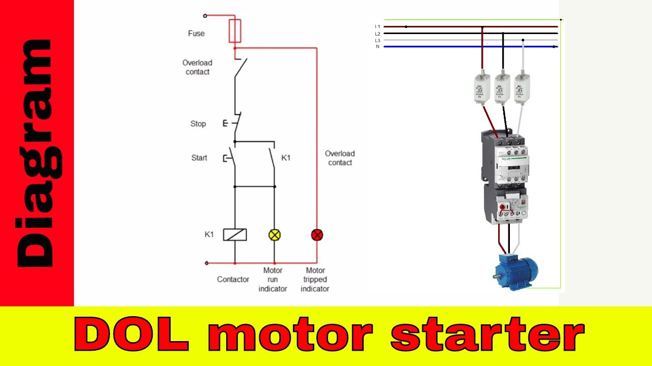
Motor starter wiring diagram. If you are not sure of how to make the connections on your equipment hire an electrician. Wiring diagram will come with numerous easy to stick to wiring diagram instructions. These guidelines will probably be easy to comprehend and apply. Star delta starter motor control with circuit diagram in hindi starter motor wiring diagram. A motor starter is a combination of devices used to start run and stop an ac induction motor based on commands from an operator or a controller. Square d motor starters wiring diagram sq d motor starter wiring diagram square d 3 phase motor starter wiring diagram square d 8536 motor starter wiring diagram every electric structure is composed of various distinct pieces.
Your motor starter may use wiring which is internal to the starter wiring which is different than the diagrams etc. In north america an induction motor will typically operate at 230v or 460v 3 phase 60 hz and has a control voltage of 115 vac or 24 vdc. Each part should be placed and linked to different parts in specific way. Figure 1 typical wiring diagram line diagrams show circuits of the operation of the controller line diagrams also called schematic or elementary diagrams show the circuits which form the basic operation of the controller. A wiring diagram is a simplified traditional photographic representation of an electric circuit. It reveals the parts of the circuit as simplified shapes and the power and signal links between the gadgets.
It really is supposed to help all of the average consumer in creating a correct method. Please refer to the manufacturers literature if in doubt.
Gallery of Motor Starter Wiring Diagram