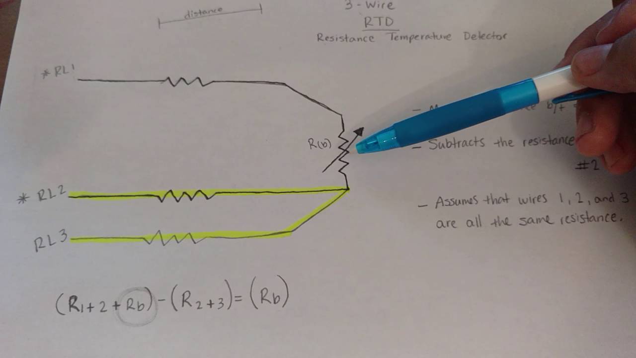
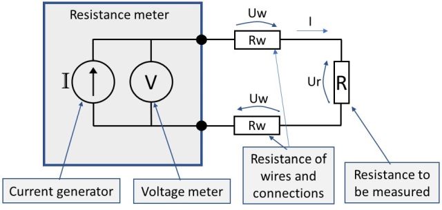
L1 and l3 carry the measuring current while l2 acts only as a potential lead. F page 3 of 5 14.
Accurate Rtd And Thermocouple Temperature Measurements See
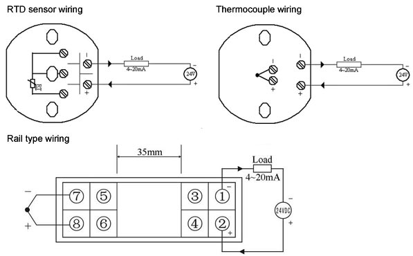
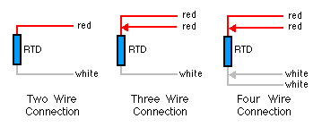
Motor rtd wiring diagram. A wiring diagram is a simplified traditional pictorial representation of an electrical circuit. 3 wire rtd wiring diagram. Rtd wiring configurations there are three types of wire configurations 2 wire 3 wire and 4 wire that are commonly used in rtd sensing circuits. And rt is the rtd. Shown is a 2 wire rtd connected to a typical wheatstone bridge circuit. The rtds used in motor windings are either 10 ohm 100 ohm or 120 ohm.
A 2 wire configuration with a compensating loop is also an option. Eo is the output voltage. 2 wire rtd connections the 2 wire rtd configuration is the simplest among rtd circuit designs. Interconnecting cable courses might be revealed around where particular receptacles or fixtures have to be on an usual circuit. Motor rtd wiring diagram what is a wiring diagram. Assortment of motor rtd wiring diagram.
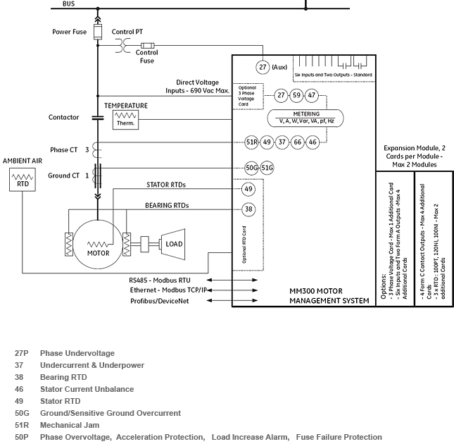
The rtds are installed in the slot portion of form wound motors and either in the slot standard or in the end turns of mush wound motors. Each type of rtd has its own particular resistance characteristic. A wiring diagram is a simplified conventional pictorial depiction of an electrical circuit. It shows the way the electrical wires are interconnected and may also show where fixtures and components could possibly be coupled to the system. R1 r2 and r3 are fixed resistors. No current flows through it while the bridge is in balancesince l1 and l3 are in separate arms of the bridgeresistance is canceled.
Es is the supply voltage. In this circuit there are three leads coming from the rtd instead of two. In this uncompensated circuit lead resistance l1 and l2 add. It reveals the parts of the circuit as streamlined shapes and the power as well as signal links in between the gadgets. Rtd technical data see also. Temperature range adjustment temperature signals are input from the 2 pt100 temperature sensors and the values of the measurement range are entered into windows m63 and m64.
It shows the components of the circuit as streamlined forms as well as the power and also signal links between the tools. The basic detectors are listed below. Sierra instruction manual series 205 innova sonic rtd wiring instructions rtd wiring instructions from appendix 3 im 205 rev. Motor rtd wiring diagram building electrical wiring representations reveal the approximate places as well as affiliations of receptacles illumination as well as long term electric solutions in a building. A wiring diagram is an easy visual representation from the physical connections and physical layout associated with an electrical system or circuit. Assortment of 3 wire rtd wiring diagram.
Gallery of Motor Rtd Wiring Diagram