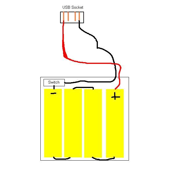
Additionally most devices can receive power in host mode even though this is not part of the standard. A lot of people wonder why have micro usb 5 pins instead of 4.

Mini Usb To Hdmi Wiring Diagram Filter 2012 Rmnddesign Nl
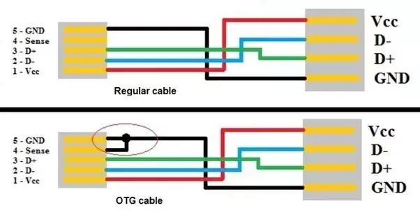
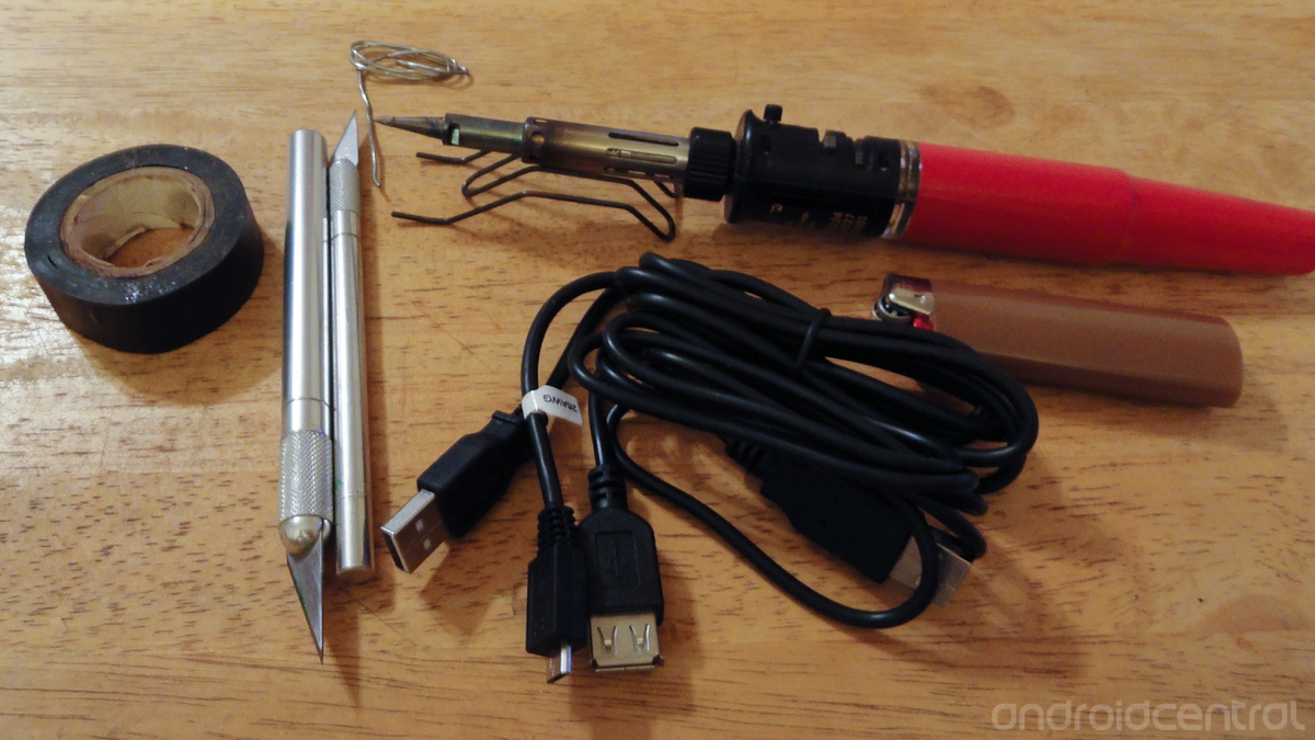
Micro usb otg wiring diagram. I made another schematic how you should wire things up so the usb will work as a host or otg mode. In addition it can link device to a power supply for charging function. The red one is for sure wire with dc ability of 5 volts. According to male mini usb to male micro usb otg wiring diagram phone you will find just four wires used in the cable. Micro usb wiring diagram wiring diagram is a simplified gratifying pictorial representation of an electrical circuit. The majority of them utilize usb cable.
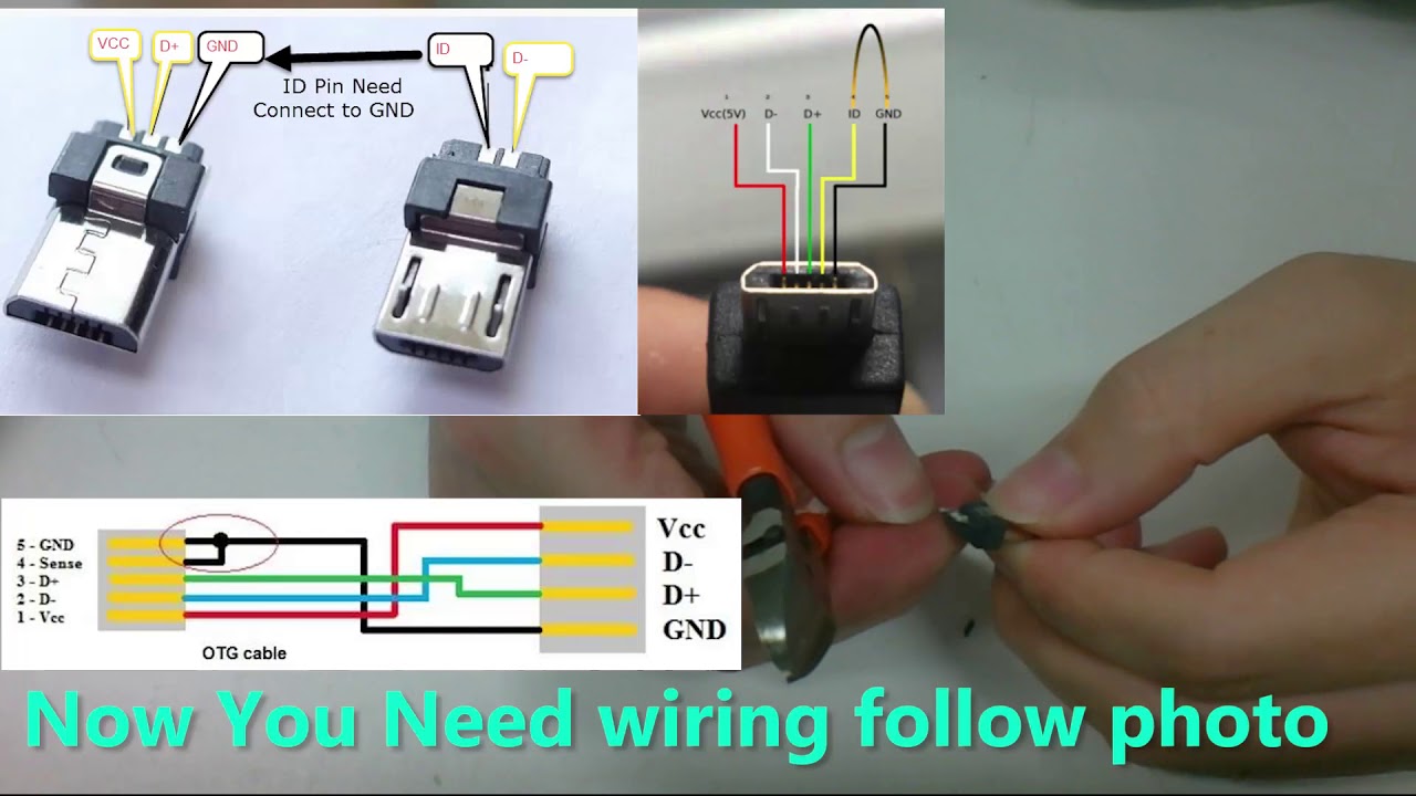
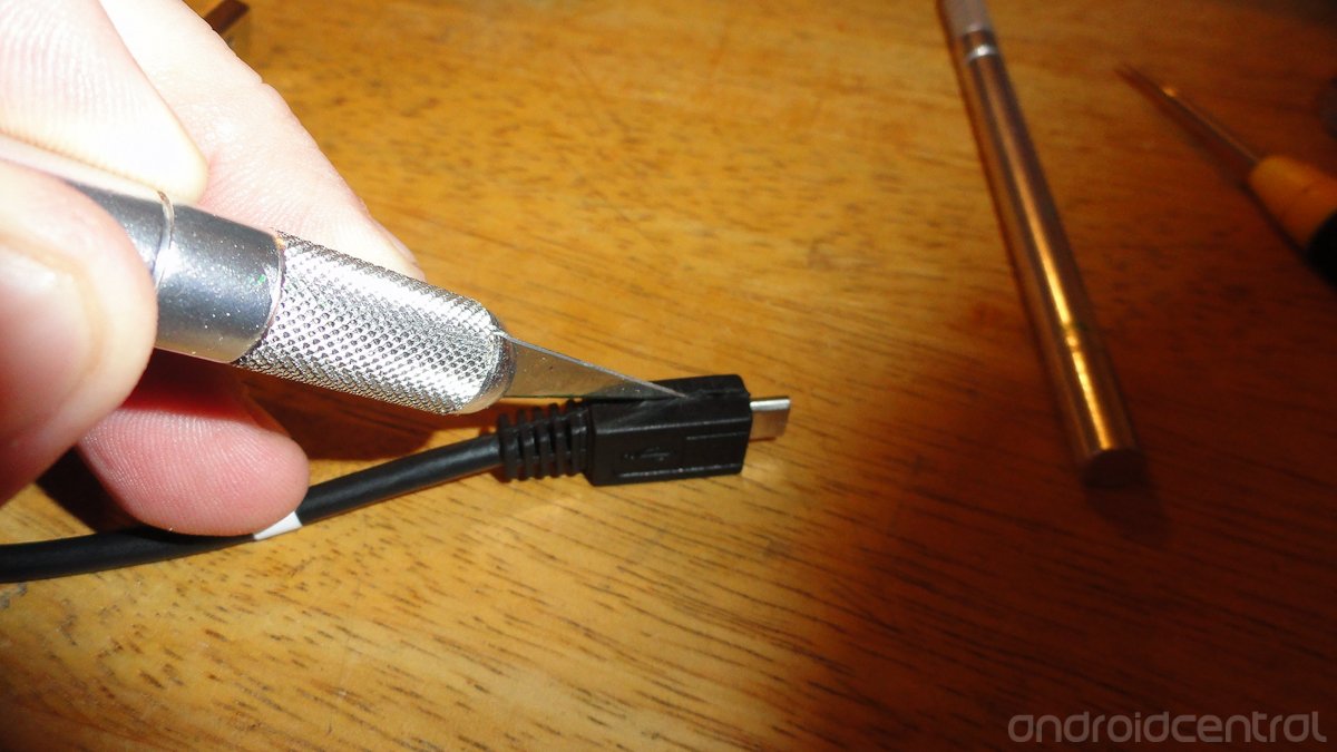
Wiring diagram for otg usb wiring diagram usb otg there are many sorts of electronic gadgets available. It shows the components of the circuit as simplified shapes and the gift and signal connections surrounded by the devices. Typically it utilizes black black red and white cable colors. Type a usb pinout diagram micro usb pinout diagram along with usb wiring diagram. It allows portable devices such as cell phones which support. Now solder the other ends of the wire on the micro usb connector.
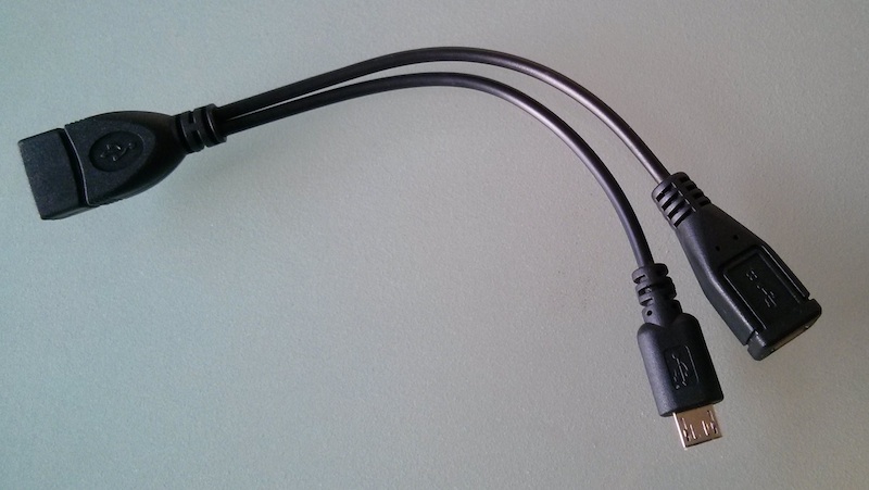
This cable is most commonly used in mobile charger for charging mobile phones and as a usb data cable to connect mobile devices to tranfer files and images between. Black wire serves as floor just like in any other device. Power delivered by micro usb 20 must not exceed 3a 20 v 60 w. Usb on the go otg introduces the concept of a device performing both master and slave roles. The cable can be used to transfer information from one device to another. Below is the figure showing the pinout diagram of the usb micro b and usb a wiring diagram.
Gallery of Micro Usb Otg Wiring Diagram