It shows the parts of the circuit as simplified forms and the power as well as signal connections in between the devices. Volts metal halide watts if i put a watts in this fixture it will.
1000 Watt Hps Ballast 1000 Watt Metal Halide Ballast 1000
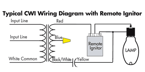
Mh ballast wiring diagram. Install encelium energy management system in 0 10v or dali platform. A wiring diagram is a type of schematic which uses abstract pictorial symbols showing all the interconnections of components inside a system. Assortment of metal halide ballast wiring diagram. Metal halide ballast wiring diagram whats wiring diagram. Collection of 1000 watt metal halide ballast wiring diagram. Collection of metal halide ballast wiring diagram.
Parallel ballasts can only be wired in parallel according to the diagram on the ballast. Quick 60 system warranty covers quicktronic ballast and sylvania lamps. A wiring diagram is a simplified conventional photographic representation of an electrical circuit. 1 lamp rapid start ballast diagram. Couple quicktronic metal halide ballasts with high performance metalarc pulsestart or metalarc powerball ceramic lamps. The ballast data tables in our catalog indicate the page number and reference letter corresponding to the correct diagram for each ballast product.
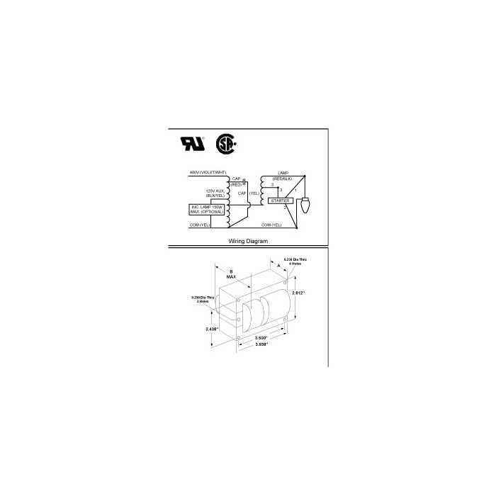
A wiring diagram is a simplified traditional photographic representation of an electric circuit. Mh ballast wiring diagram 100w mh ballast wiring diagram 150w mh ballast wiring diagram 400w mh ballast wiring diagram every electrical structure consists of various different pieces. Wiring diagrams metal halide mh and watts position new ballast in ballast housing with wires located 50 70 and watts. Wiring diagrams for venture standard metal halide ballast products are provided on this page. The mercury vapor ballast wiring diagram is the blueprint for the ballast circuitry including the input supply voltage and grounding methods. Quick 7xl tm covers quicktronic prostart r ballasts and several sylvania lamps.
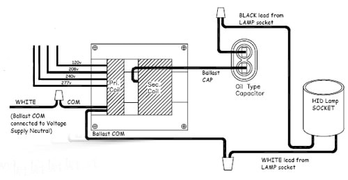
Changing the wiring on a fluorescent light fixture from series to parallel involves changing the ballast from a series to a compatible parallel ballast. It reveals the parts of the circuit as simplified shapes and the power and signal links in between the gadgets. A wiring diagram is a streamlined standard photographic representation of an electric circuit. Wiring diagrams include a couple of things. It shows the components of the circuit as simplified forms as well as the power as well as signal connections in between the gadgets. Ballast wiring diagrams for hid ballast kits including metal halide and.
Standard metal halide hps ballasts brackets wiring diagrams warranty information. A ground connection must be made to all ballasts to avoid shock hazard personal injury or damage to the luminaire or installation. Symbols that represent the components within the circuit and lines that represent the. If not the arrangement wont work as it ought to be. Each component should be set and linked to other parts in specific manner.
Gallery of Mh Ballast Wiring Diagram