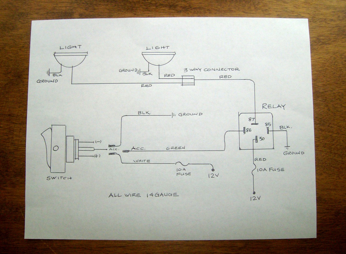
The wiring diagram to the right will show how to wire and power this 12v 20amp on off on 3 way carling contura rocker switch. The basic function test according to the logic diagram provides electrical.
185 Active Guitar Pickup Wiring Diagram 3 Wiring Library
Mafelec switch wiring diagram. Need a installation diagram for a dump moter for f diesal bought a new motor for the controller is made by mafelec. 49 06 22 89 20 50. Mafelec gmbh switzerland schwimmbadstrasse 4 ch 5210 windisch switzerland tel. Petercem 14 za des 4 vies 38 290 frontonas france tel. 49 06 22 89 20 50. 20122018 20122018 5 comments on mafelec 3 switch wiring diagram interior.
The pump and motor unit for this lift can require up to 205 amps of electrical power at 12 volts dc. 41 056 461 68 68. When wiring this switch you can choose if youd like to illuminate it because of the independent lamp attached to terminals 8 and 7. 33 04 76 32 07 33. L the schematic or line diagram includes all the components of the control circuit and indicates their. Or these terminals can be ignored for non backlit switch banks.
Get free help tips support from top experts on mafelec control box related glove box door. Mafelec 3 switch wiring diagram interior. 41 056 461 68 68. Petercem 14 za des 4 vies 38 290 frontonas france tel. The control box will be just inside the glove box to the top. Mafelec 471 route de la cuisinière 38 490 chimilin france tel.
Comtronic in den kreuzwiesen 26 69250 schoenau germany tel. Comtronic in den kreuzwiesen 26 69250 schoenau germany tel. Wiring installation instructions railgate railgate important. Mafelec gmbh switzerland schwimmbadstrasse 4 ch 5210 windisch switzerland tel. 33 04 76 32 07 33. In this diagram two 3 way switches control a wall receptacle outlet that may be used to control a lamp from two entrances to a room.
The source is at the sw1 where the hot is connected to. 4 floor 16 more 635mm push 8 floor 32 more 635mm push. Dismantling the old rotary switch. Mafelec k4 series 433 155 dc switch. Typical wiring diagrams for push button control stations 3 genera information at each circuit is illustrated with a control circuit continued schematic or line diagram and a control station wiring diagram. Be sure you connect the black cable to the negative terminal of.
Electrical diagram n the wiring leaves the case through new rotary switch mafelec. Tommy gate hydraulic lift the original r to the installer. 3 way switched outlet wiring. Three wire cable runs between the switches and the outlet. Ok there is a switch on the dash that retracts and extends the foot pedals so you can move. In accordance with this diagram your warranty will be void.
This circuit is wired the same way as the 3 way lights at this link. Mafelec 471 route de la cuisinière 38 490 chimilin france tel.
Gallery of Mafelec Switch Wiring Diagram