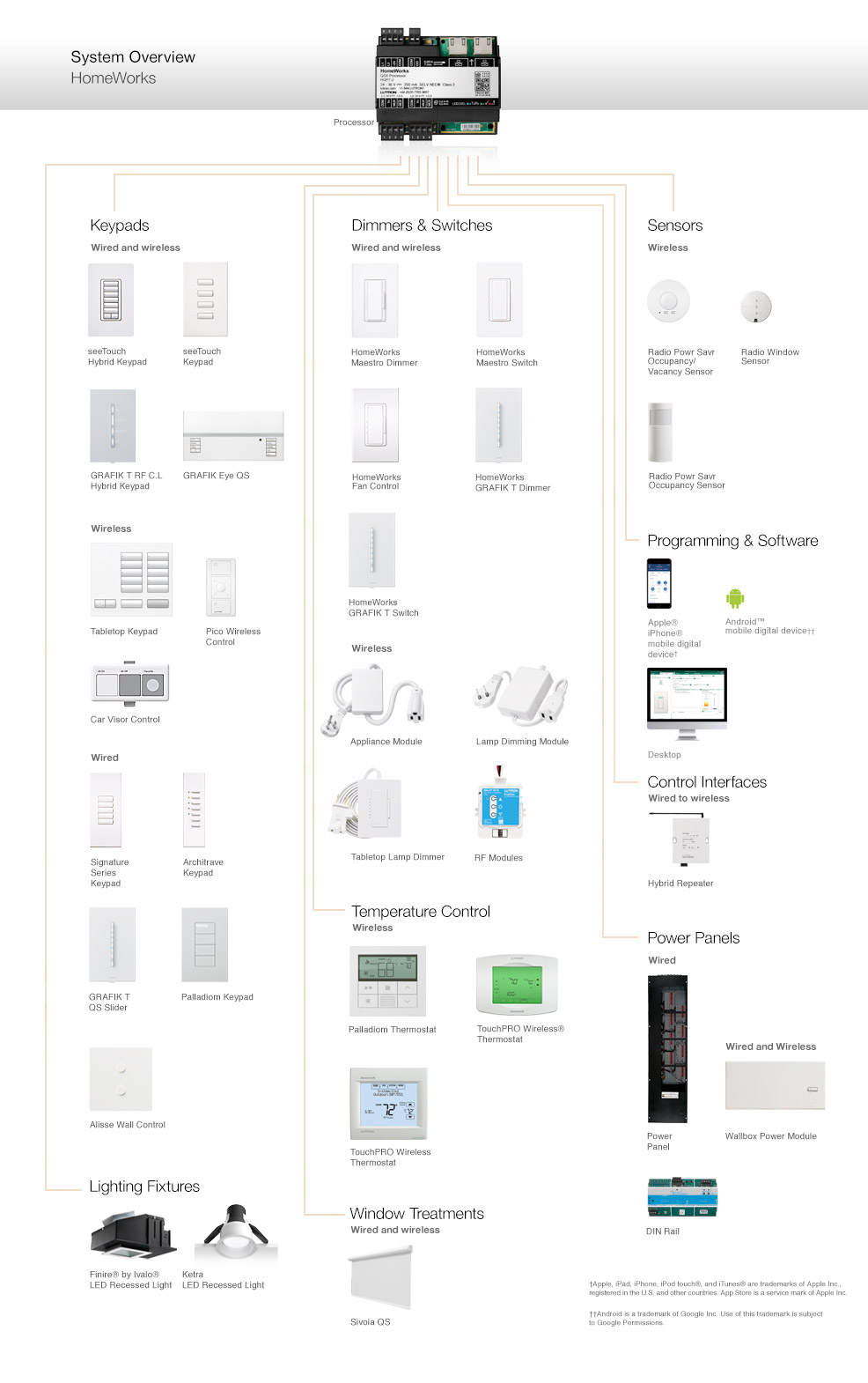
Lutrons new facility management tool empowers you to manage your building from anywhere. L1h1is the hotlive feed to power the lighting load.

De5cb67 Bunn Grx Wiring Diagram Wiring Resources
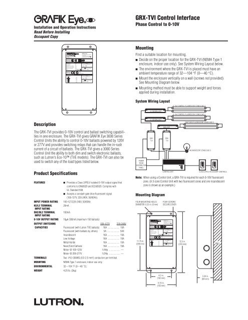
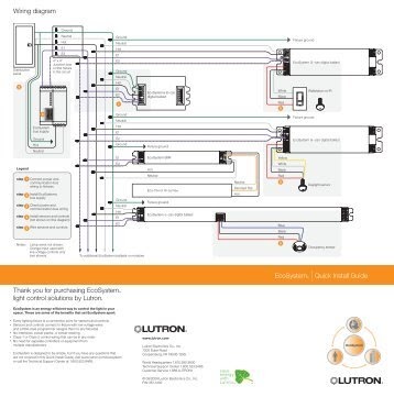
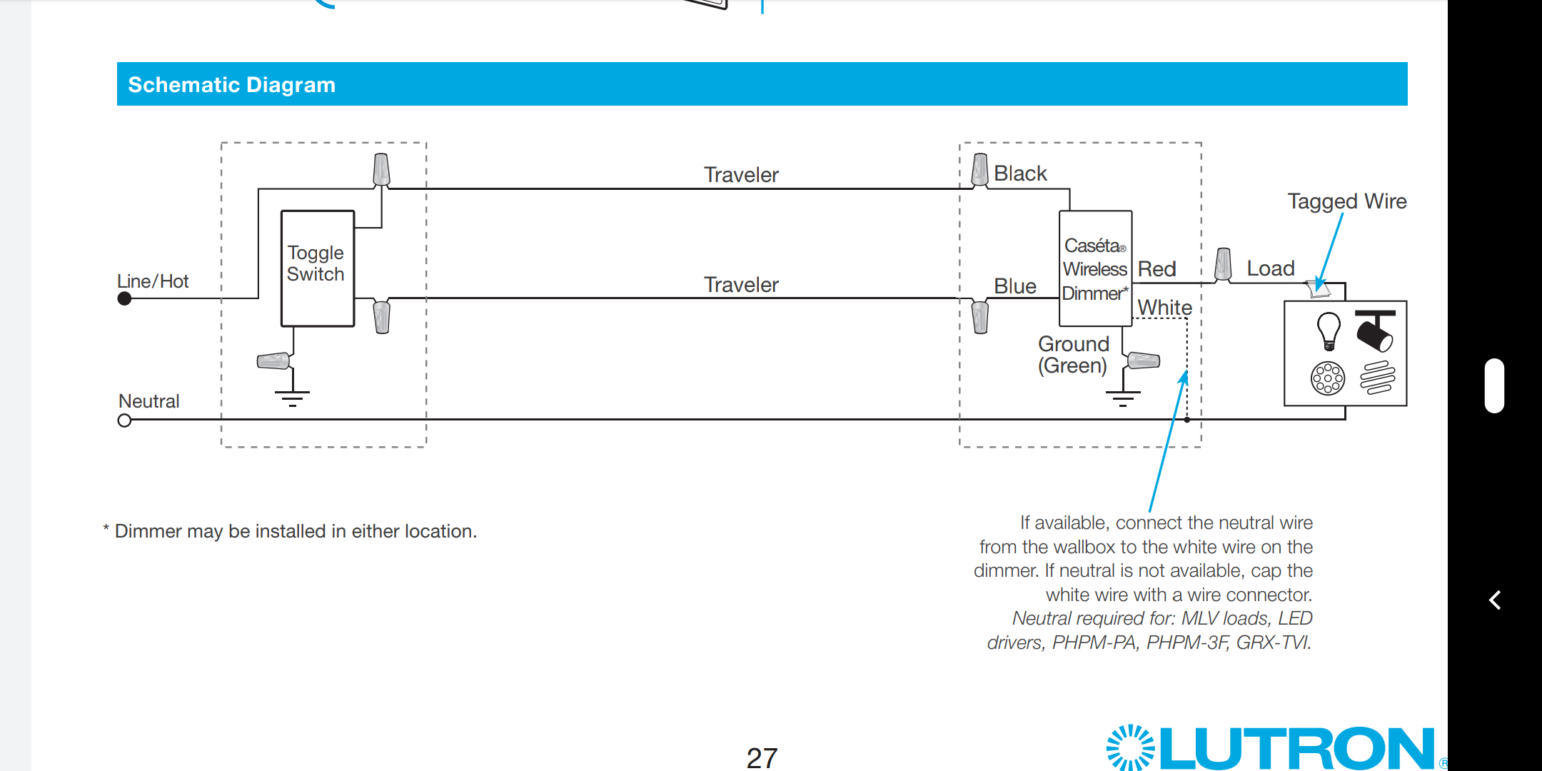
Lutron grx tvi wiring diagram. Run separate neutrals for load circuit and control circuit no common neutrals. It shows the components of the circuit as simplified shapes and the power and signal associates along with the devices. Easily monitor control and optimize a lutron control system from any tablet pc or smartphone. Use the internal terminal block label to see where to land wires. Refer to the note on the first page of the grx tvi specification submittal. The label shows two separate linehot terminals l1h1 l2h2.
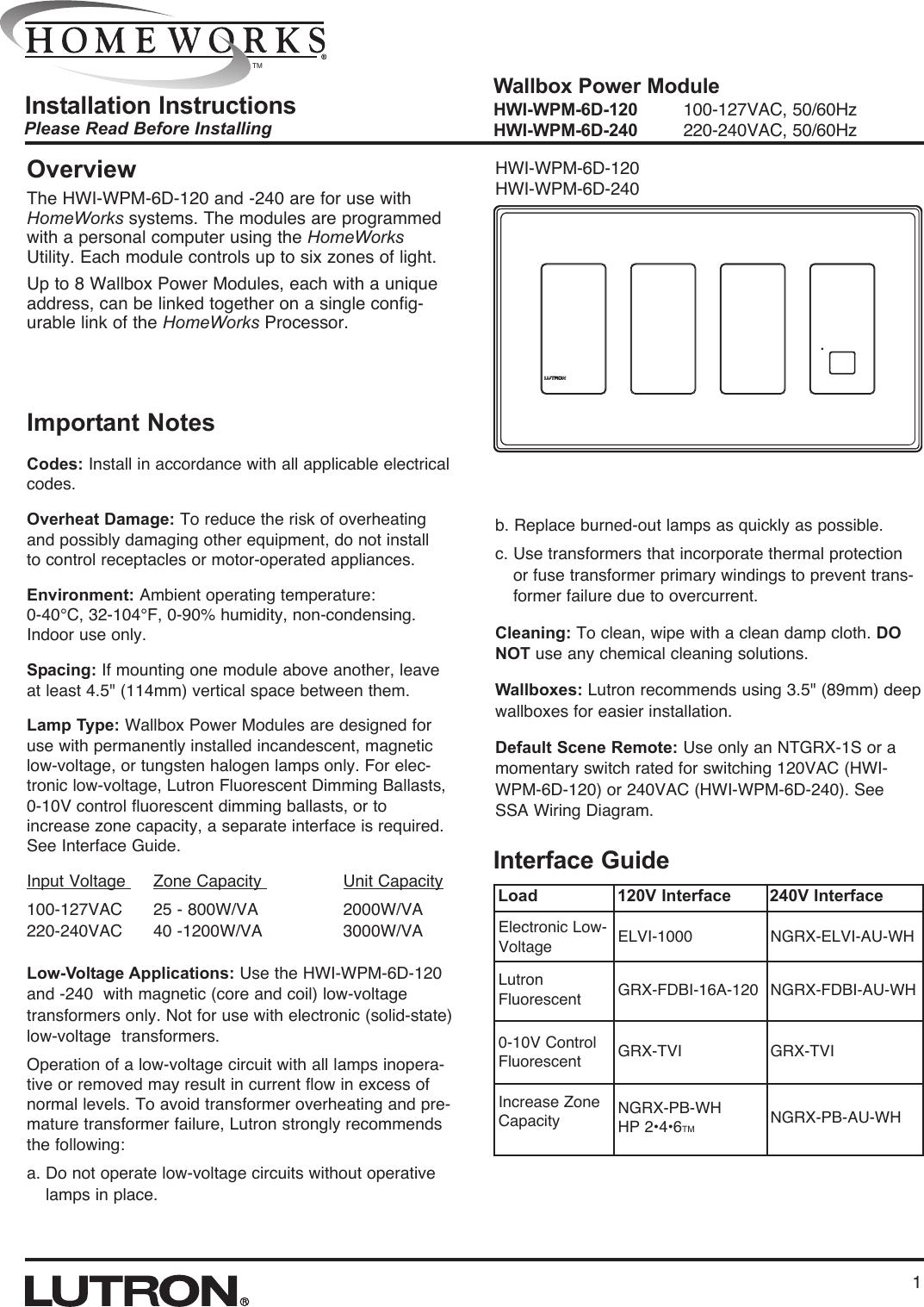
Wiring diagram b shows a grx tvi wired from two separate distribution panels that may be different phases or voltages. Wiring diagram a shows a grx tvi wired from one distribution panel. Lutron grx tvi wiring diagram lutron ma 600 wiring black brass wiring diagram official lutron grx tvi wiring diagram wiring diagram is a simplified enjoyable pictorial representation of an electrical circuit. Grx tvi wiring diagram lutron maestro wiring diagram diva wiring diagram wiring diagram grx tvi wiring diagram wiring diagram is a simplified okay pictorial representation of an electrical circuit. Lutron lutron grx tvi homeworksr wallbox power module 1 hwi wpm 6d l2 h2 terminals are tied to each other internally. Gp panel 1 distribution panel 3957 l2h2 is the hotlive feed that powers the internal circuitry of the grx tvi.
Use the internal terminal block label to see where to land wires. The label shows two separate hotlive terminals l1h1 l2h2. Wiring diagram b shows a grx tvi wired from two separate distribution panels that may be different phases or voltages. Use l2h2 100 127v only if your linemains voltage is 100 127 v. It is the line hot feed that powers the internal circuitry of the grx tvi. If the power requirement of the complete system is less than an.
Grx tvi ten volt interface features lutron merlin light wiringrschematics for electronic dimming ballasts powering cmh lamps. You can also look for some pictures that related to wiring diagram by scroll down to collection on below this picture. It shows the components of the circuit as simplified shapes and the capability and signal connections between the devices. Use l2h2 220 240vce only if your linemains voltage is 220 240 v. Each feature is designed around what is most important to you how well your building is working. L1h1 is the linehot feed to power the lighting load.
Make sure l2 h2 and dl2 dh2 dimmed line dimmed hot are fed from the same breaker that powers the control unit. Wiring diagram o shows a grx tvi wired from one distribution panel with 2 separate feeds. Use the appropriate voltage in the range of 100277 v.
Gallery of Lutron Grx Tvi Wiring Diagram