A connect a hot wire 12 volts to the b terminal of the flasher unit. 12v 3 terminal electronic flasher unit fl3 12 volt electronic flasher unit with 3 terminals marked 19 31 49a.
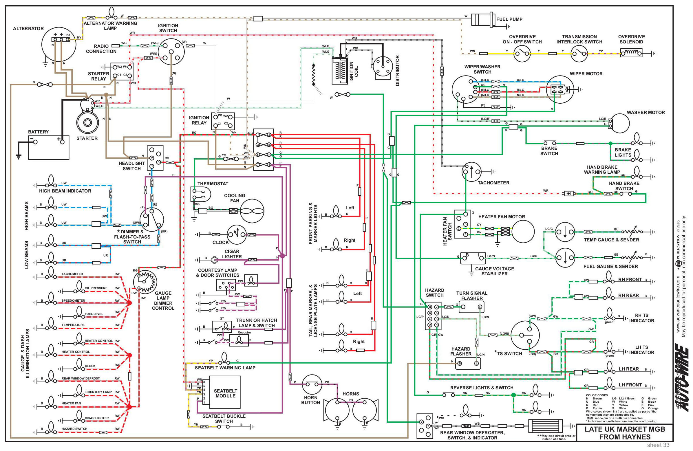
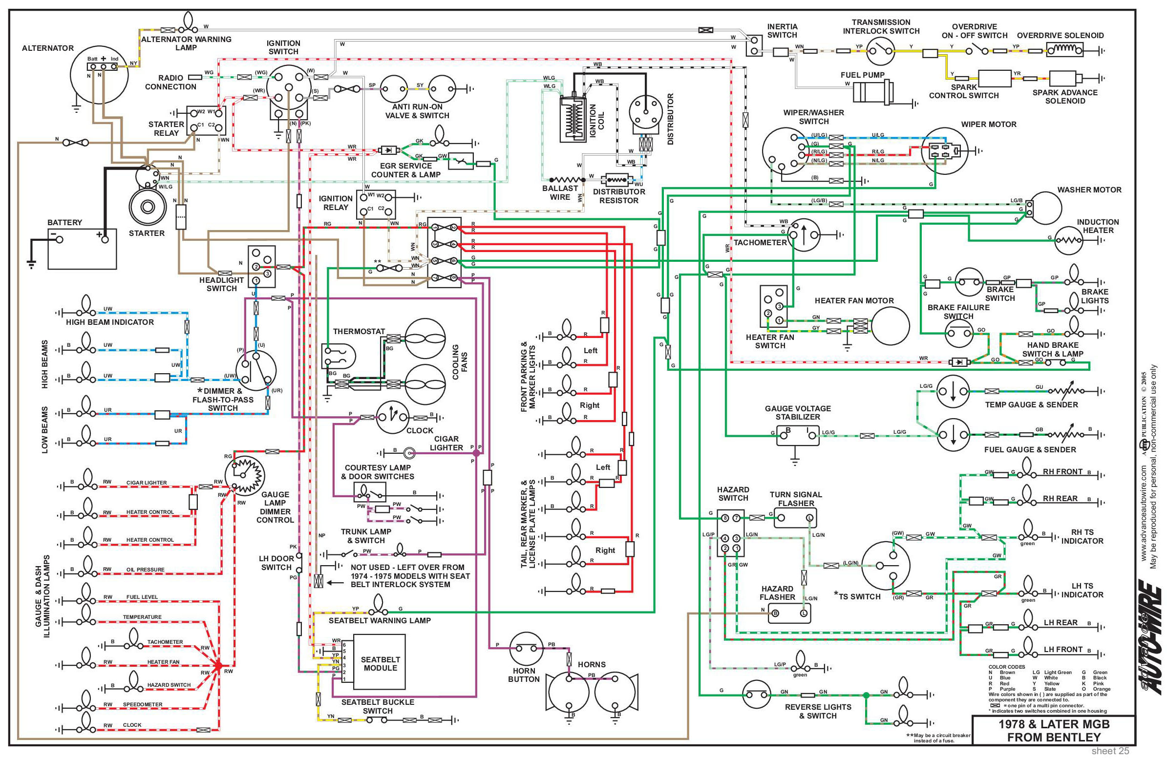
Wiring Diagrams
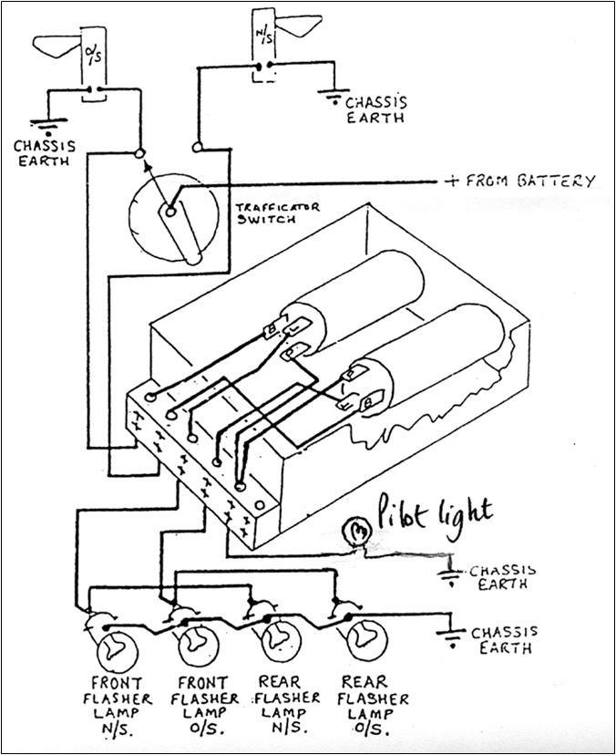
Lucas flasher unit wiring diagram. Based on a page by chris kantarjiev of the dimebank garage with several additions and modifications by skye nott. Flasher relays are often wrongly blamed for faults on the indicator circuits of cars and motorcycles. To test the flasher unit do the following. Another of the new basic skills family of short videos. Collection of 3 pin led flasher relay wiring diagram. This unit needs to be wired in conjunction with a suitable flasher unit and brake light switch.
1 together with an easy to follow wiring diagram fig. This short video shows how to wire. The clip should be fitted direct to vehicle body with a self tapping screw. The flasher unit clip should be removed from the bracket and used to retain the flasher unit close to the switch. Size 40mm x 30mm x 30mm. Wiring connections disconnect the battery whilst carrying out any wiring work.
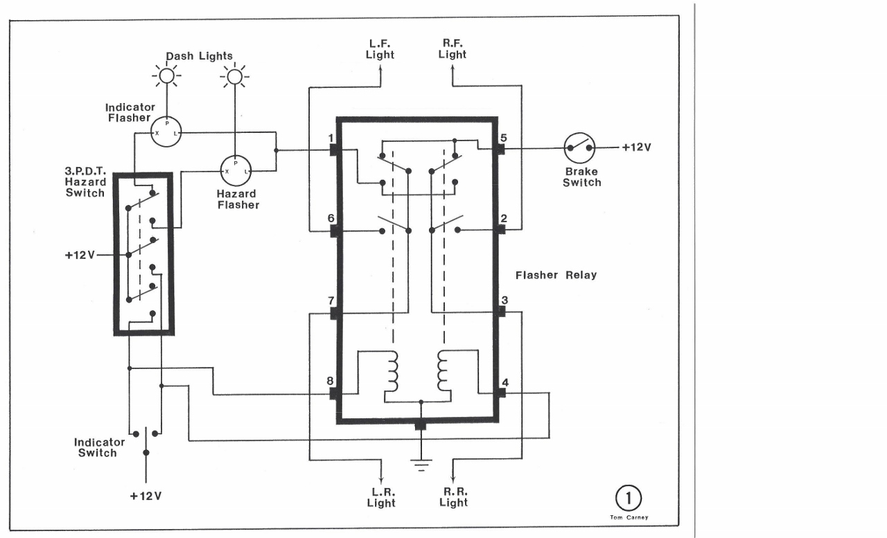
3 x 63mm blade terminals marked b p l. You may find it helpful to enlarge the page to 11x17 with a photocopier and trace circuits with coloured pencils. It reveals the elements of the circuit as streamlined forms and the power and also signal links between the devices. Replaces lucas fl5 b power in p feed to warning lamp l flasher signal out. Any manual should have a wiring diagram haynes is fine. Wiring them up is not a difficult task but to help those who are a little unsure of the procedure we are grateful for the following article supplied by our colonial correspondent which explains the working of the flasher unit fig.
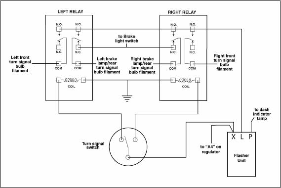
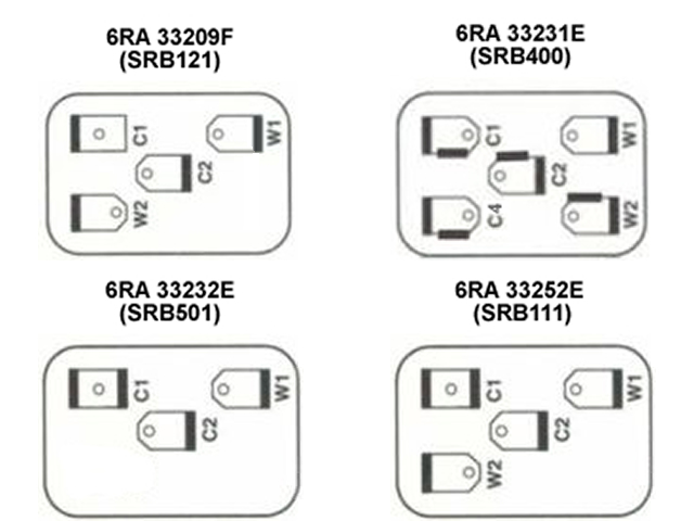
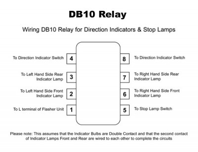
To enable brake lights to be used as rear indicators. Lucas 33117 or db10 style flasher unit. Similar to lucas sfb170 sfb182 and sfb190 suitable for most cars with a 12 volt system. Lucas sfb105 flasher unit. 8 x screw terminals. Supplied with wiring diagram.
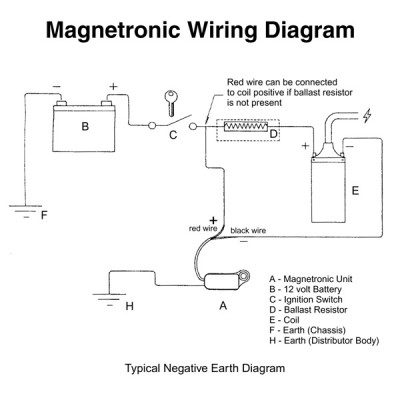
A wiring diagram is a simplified conventional photographic depiction of an electric circuit. Can be used for both positive and negative earth vehicles. Connect the purple wire to a suitable 12v permanent live source. Aluminium can with integral mounting bracket. Flasher unit sfb162 lamps to produce synchronised flashing lamps to produce alternating flashing lamps lucas flasher units guide suggested wiring combinations 14 030 87 86 85 87a 30 14 030 relay 14 030. 12v only negative or positive earth.
In the car you might just switch on the ignition and use a test light to verify that power is connected to the flasher in the car.
Gallery of Lucas Flasher Unit Wiring Diagram