Pd132 loop detector specificationver100 4 use and operational on powering the pd 132 loop detector it will automatically calibrate. The wire should maintain its integrity under the pavement stress.
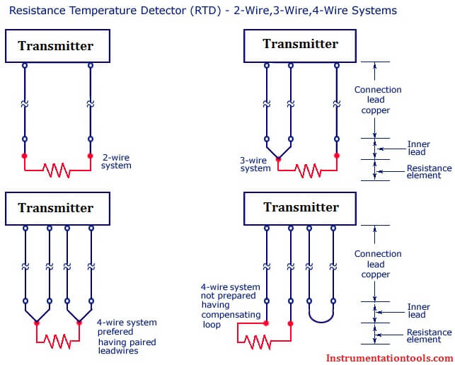
Difference Between 2 Wire Rtd 3 Wire Rtd And 4 Wire Rtd S
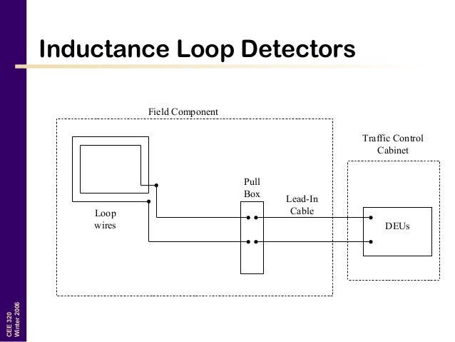
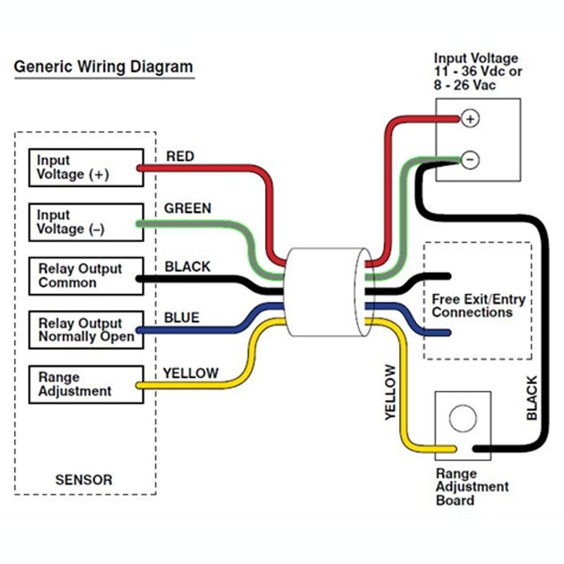
Loop detector wiring diagram. A wiring diagram is a streamlined conventional pictorial representation of an electrical circuit. The wire gauge is not critical to proper operation of the loop detector. First remember that the loop is an integral part of the detector electronic circuitry. A wiring diagram is a streamlined traditional photographic representation of an electric circuit. Assortment of loop detector wiring diagram. It shows the components of the circuit as streamlined forms and the power as well as signal links between the gadgets.
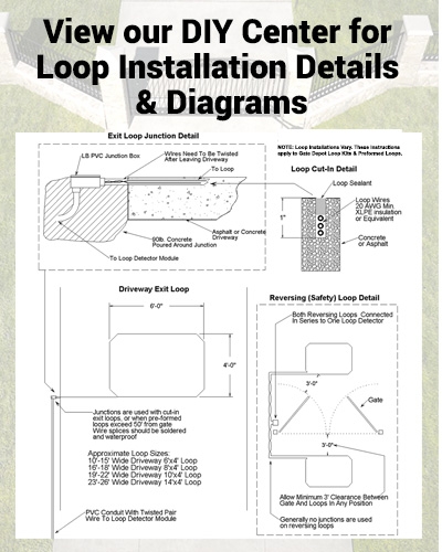
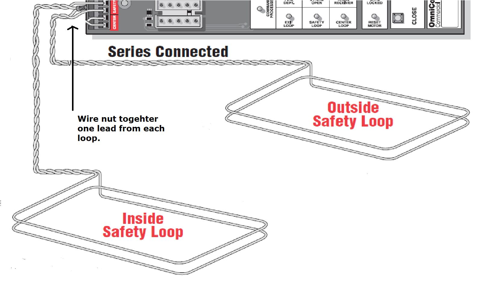
The home run to the pull box shall be requirements of imsa. We the loop detector manufacturers entrust you with making a very important electronic part of our loop detector. Loops with same one or two turns conductor cable no. Collection of loop detector wiring diagram. When correct it will show 2 leds. The loop wire should be 16 gage stranded.
Do not leave a car on the loop or any other metallic objects when it is calibrating. Materials used in the construction of the loop are important. 14 stranded single conductor wire which meet the requriements of imsa. A wiring diagram normally gives details concerning the loved one setting and setup of gadgets as well as terminals on the gadgets to help in building or servicing the tool. It reveals the parts of the circuit as simplified forms as well as the power and signal connections in between the devices. Loop wire above and below number indicates wired in series detector no.
Since asphalt is more flexible than concrete it is recommended that a heavier gauge wire be used for loop installations in asphalt.
Gallery of Loop Detector Wiring Diagram