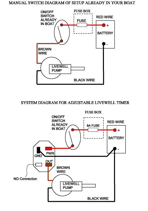
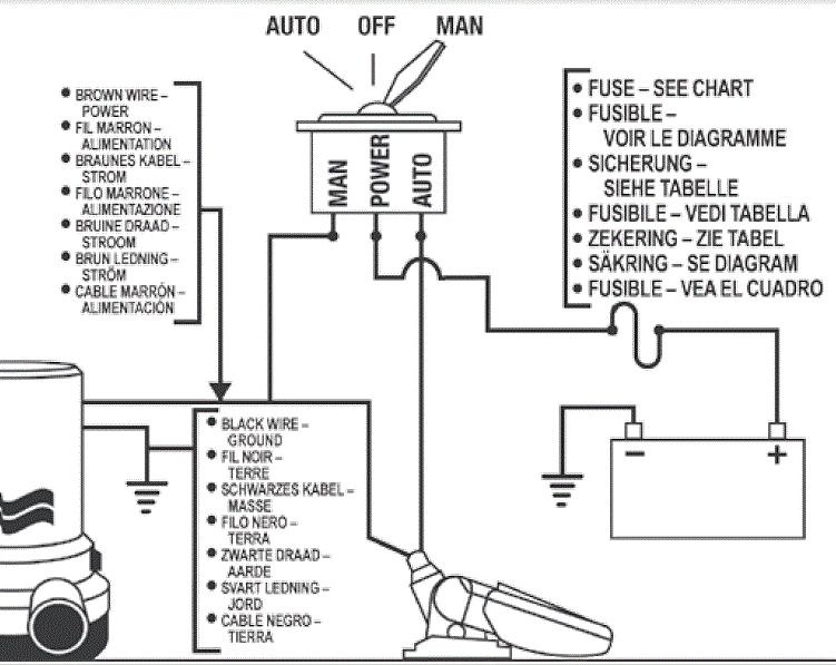
Livewell timer installation instructions. The red wire connects to the battery positive the black wire connects to the pump.
Lovett Bilge Pump Wiring Diagram Diagram Base Website
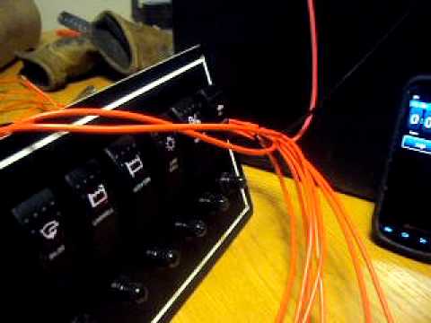
Livewell timer wiring diagram. Livewell timer installation diagram installation diagram how to install livewell timer how to wire a livewell timer livewell timer wiring diagram. Leave the plastic connector cover in place black square in middle of timer to connect your adjustable livewell timer into your current boat you will need to buy some 16 gauge wire i recommend buying 3 different colors. Rigrite makes livewell timers grommets marine fuse holders quick part 16 ga. Of these simple instructions will help you to obtain maximum enjoyment from your new boatlivewell switches and wire diagramlivewell switches and wire diagram. After mounting panel string wire to battery and pump areas. In the event that you have an electrical issue with your switch you can find the electrical wiring diagram for the stratos boats livewell switch here stratos aerator switch wiring diagram.
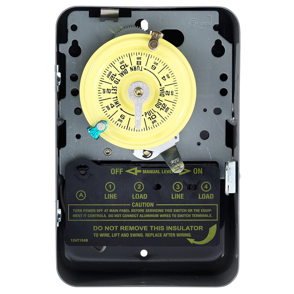
Livewell timer module wiring diagram wiring diagram is a simplified within acceptable limits pictorial representation of an electrical circuit. 6002 livewell control center hook up diagram installation select a location for mounting the control panel cut a hole 1 78 x 1 58 see sheet 2 secure panel with 8 sheet metal screws. One for power red one for ground black and one for the pump brown. Wire w10 amp fuse view switch wiring diagram. This pdf covers several models of stratos boats. Livewell timer wiring electronics.
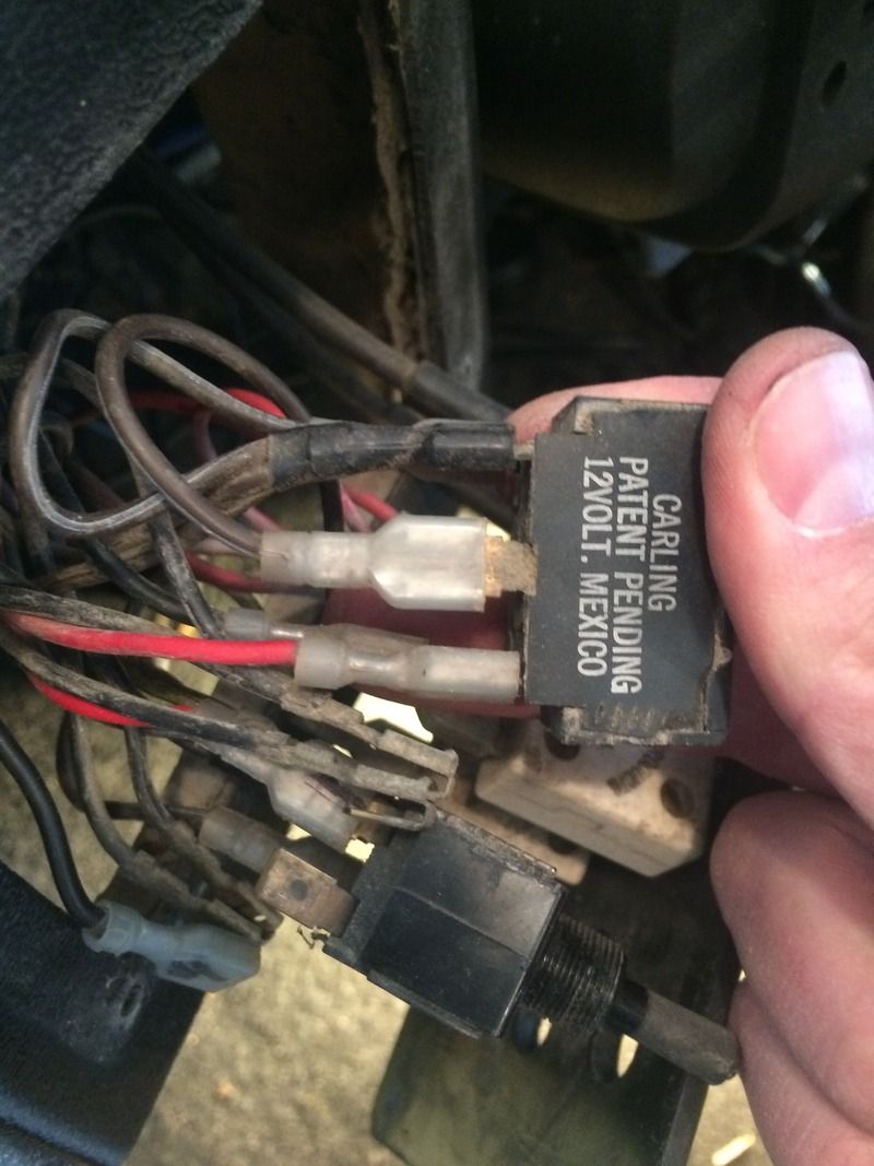
The extreme series is the upper left diagram. It shows the components of the circuit as simplified shapes and the power and signal friends in the midst of the devices. Jun 18 my buddy has a skeeter sx he is trying to replace switches for his livewell manual a timer but for some reason he has hook up all the wires in wrong poles on his switches.
Gallery of Livewell Timer Wiring Diagram